In this part of the tutorial, create the joystick handle by revolving a profile curve.
Open the tutorial file
- Choose File > Open
 to open the file browser.
 - In the file browser, locate the CourseWare folder and set it as the Current Project.
- Open the file called joystick.wire, located in the wire folder in the CourseWare project.
For information on how to open a file, see Open the tutorial file.
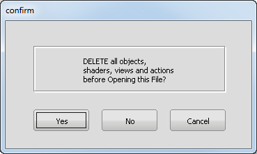
A dialog box appears, asking if you want to delete all objects, shaders views, and actions. Click Yes.
If your values for construction tolerances differ from the values in the joystick.wire file, you are presented with a dialog box:
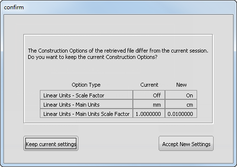
Click Accept New Settings to use the construction tolerances in joystick.wire.
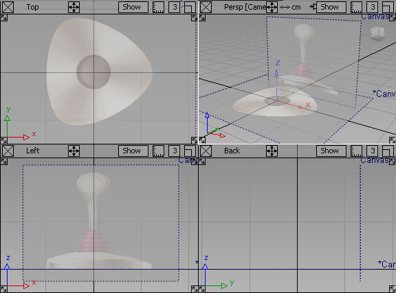
The file opens.
 Note:
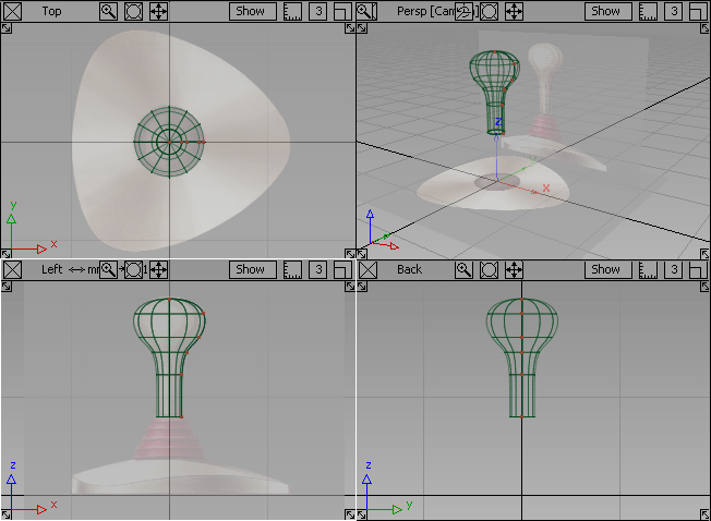
Note:The scene contains two reference images on canvas planes. Use these images as guides to model the joystick.
If you do not see any images, choose WindowDisplay > Toggles > Canvas Planes
 to turn on the display of canvas planes.
 To turn off the borders for canvas planes, choose WindowDisplay > Toggles > Construction Objects
 .
. If the modeling views do not occupy the full size of the Alias window, choose Layouts > All Windows > All Windows
 .
.
Create the joystick handle
Start by creating a curve that follows the profile of the joystick handle, which you will later use to revolve a surface for the handle.
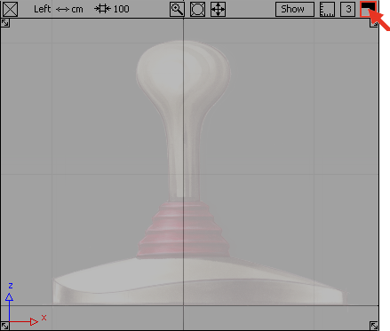
- Maximize the Left view by clicking the square icon on the top right of the Left view window.
- Choose Curves > New Curves > New CV Curve
 .
. This tool allows you to create a curve by placing control vertices (CVs, for short). CVs control the shape of a curve.
- Turn on grid snap mode by holding down the
 (Windows) or
  (Mac) key, and click the
  on the grid intersection at the top of the handle.
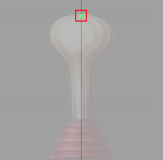
A control vertex appears.
This CV is the first of the curve and displays as a small box.
- Create the second CV. Press and hold the
 to the right of the first CV. Drag to position the CV, then release the .
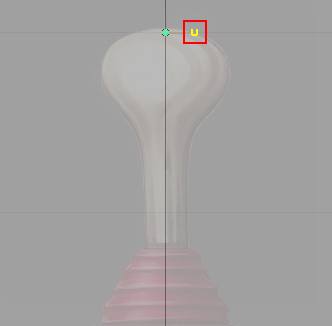
The second CV displays as a small U.
By using the
, the second CV is horizontally aligned with the first CV. Having these two CVs aligned horizontally helps to avoid a bump or dimple in the top when you revolve the surface. Note:The straight red line joining the first and second CVs is not the curve. It is the hull. Hulls connect all the CVs on a curve.
- Create the third CV. Press and hold the along the edge of the joystick handle outline. Drag to position the CV and then release the .
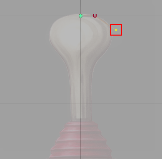
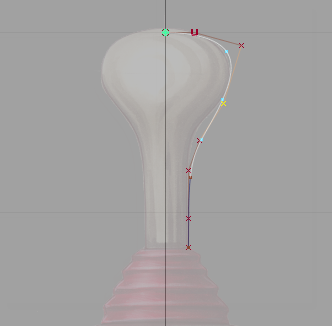
The third CV appears. This CV and all further CVs on the curve display as small crosses. The hull now consists of two straight line segments between the first, second, and third CV.
- Create the fourth CV. Press and hold the along the edge of the handle outline. Drag to position the CV and then release the .
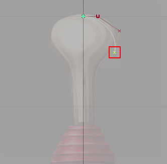
The fourth CV appears.
A white curve now connects the first CV and the fourth CV. The hull now consists of three straight line segments that connect all the CVs together.
Do not worry about the shape of the curve. Later, you will adjust the position of each CV to change the shape of the curve.
- Continue to place four more CVs in the following positions to complete the curve.
- Choose Pick > Nothing
 to complete the curve and unpick it.
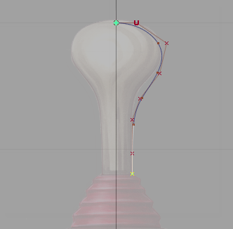
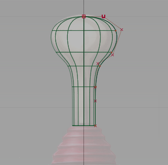
Edit the handle profile curve
Now move CVs to edit the shape of the profile curve to match the reference image.
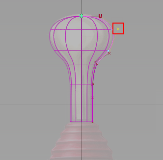
- Choose Pick > Point Types > CV
 .
. - Click the third CV or drag a pick box around it using the .
Remember, CVs do not lie on the curve; they lie on the hull.
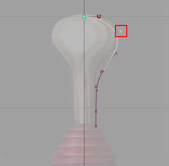
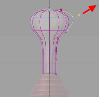
- Choose Transform > Move
 . Drag with the to move the CV so that the curve lies directly on the edge of the handle sketch.
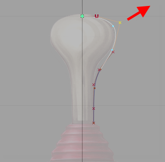
- Click the fourth CV to pick it.
- With the Move tool still active, drag with the to move the CV so the curve lies on the edge of the handle sketch.
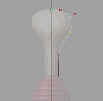
- Continue picking and moving CVs until the curve matches the sketch.
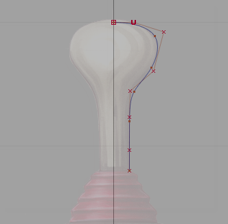
- Choose Pick > Nothing to complete the curve and unpick it.
Revolve the handle profile curve
Next, create a surface for the joystick handle by revolving the profile curve.
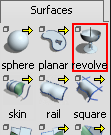
- Choose Surfaces > Revolve
 .
. 
On the prompt line, which is just below the menu bar, you are prompted to enter an axis to revolve around, select a vector, or select a curve to revolve.

- Double-click the Revolve tool icon. The Revolve Control options window opens.
- Select Periodic to so that the surface created is a closed, 360 degree revolution surface.
- Under Axis Options, select Z to revolve the curve around the Z axis.
- Click the curve.
The curve revolves and a surface is created.
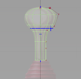
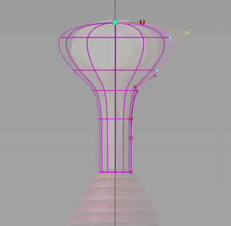
When you initially create a surface of revolution, it has two blue manipulators. These manipulators enable you to change the sweep of the profile curve and the angle of the revolution axis easily. The surface you have created is correct, and so do not adjust the manipulators.
- Choose Pick > Nothing to unpick the surface.
The manipulators disappear.
Modify the handle curve and surface
Most surfaces you create in Alias have what is known as construction history. Construction history allows you to change a surface easily after you have created it.
For example, if you move a CV on the original profile curve, the revolved surface automatically updates.
Next, move a CV to see the effect of construction history.
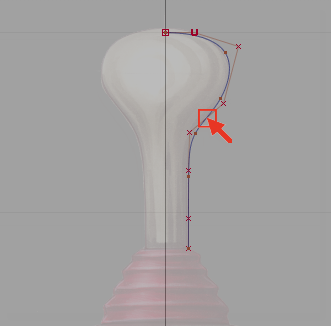
- Pick the third CV. Choose Pick > Point Types > CV and click the CV.
- Choose Transform > Move and drag with the to move the CV slightly.
When you release the mouse button the revolved surface automatically updates.
- Choose the Edit > Undo
 tool, or the hotkey
  + Z (Windows) or + Z (Mac) to undo the move.
 The surface is now complete, so next, turn off the CV display for the curve.
Tip:If you do not need to use the CVs, it is good practice to turn them off for curves and surfaces. Turning of CVs helps to reduce clutter on your screen and makes your model easier to view. It is easy to turn them back on.
On the Control Panel on the right of your screen is a Display section.
Tip:If the Control Panel is not displayed, choose Windows > Control Panel
 to make it visible.
 In the Display section, the CV/Hull checkbox indicates that the CVs and hulls are currently visible.
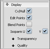
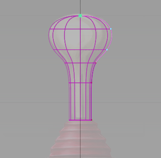
- With the CV still selected, click the CV/Hull checkbox to remove CVs from the curve display.
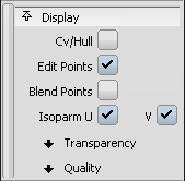
The CVs and hulls no longer display in the view.
- Choose Layouts > All Windows > All Windows to return to the four views.
 Tip:
Tip:F9 is the hotkey for Layouts > All Windows > All Windows
. Use F9 to set the screen to show all four views at any time.
Save your work
Now save the scene as a new file.
- Choose File > Save As
 . The file browser opens.
 - In the file browser, locate the Lessons folder. Set the Lessons folder as the Current Project.
- Save your work in the wire folder of the Lessons project.
- Name your file myjoystick_Part1.wire.
For information on creating the Lessons project, or saving your work, see Save your work.