In this part of the tutorial, create the joystick base with skin and planar surfaces.
Open the tutorial file (optional)
If you successfully completed part 1, you can proceed directly to the next step, Create the base outline curve.
If you were not successful in part 1, open the file called joystick_Part1.wire, located in the wire folder of the CourseWare project. This file contains the completed model from part 1.
Create the base outline curve
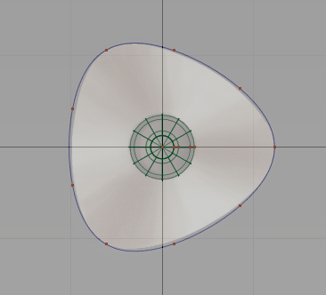
First create a rounded triangle shape from a primitive circle.
- Maximize the Top view. Choose Layouts > Top
 . Tip:
F5 is the hotkey for Layouts > Top
. 
- Choose Curves > Primitives > Circle
 .
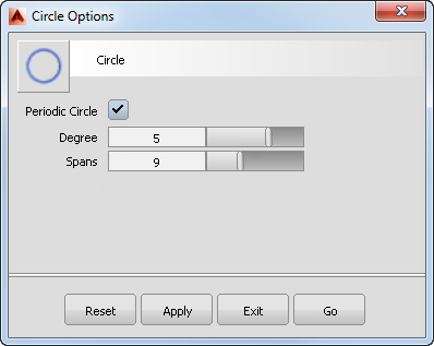
. - Double-click the Circle tool icon. The Circle Options box opens..
In the Spans box, the default number of sections is set at 12. For this triangular shaped base, nine spans are sufficient.
Type 9 in the Spans box and click Go.
- Turn on grid snapping by holding down the
 (Windows) or
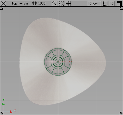
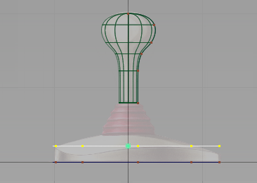
  (Mac) key. Click near the origin (where the two dark grid lines intersect) to place the circle at the center of the base.
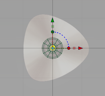
A small circle is placed at the origin. The manipulators are shown, but you will not use them for this part of the tutorial.
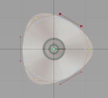
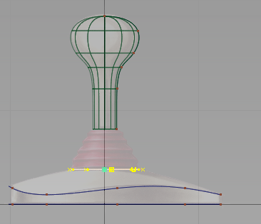
Next, scale and reshape the circle to form the base outline.
- Choose Transform > Scale
 . The manipulators disappear.
 - Make the circle larger.
Click and drag with the
 towards the top right corner of the screen. Match the size of the circle to the inside of the base outline, as shown in the following image.
 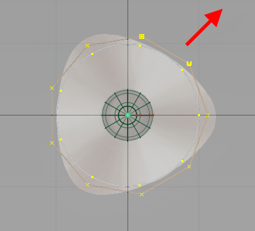 Tip:
Tip:Use the screen diagonal direction for an increase or decrease in scale. Drag towards the bottom left corner to decrease the scale. Drag towards the top right corner to increase the scale.
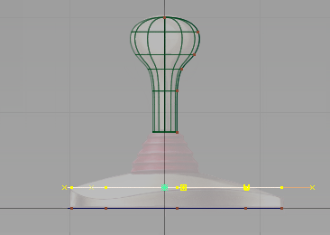
- Choose Pick > Nothing
 to deselect the circle.
 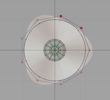 Tip:
Tip:Check that the CV shown as a U is at the right side of the circle. If the U CV is at the left, you inverted the circle while scaling. Scale the circle again, being sure to click and drag towards the top right of the screen.
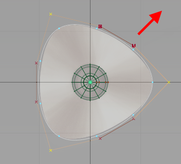
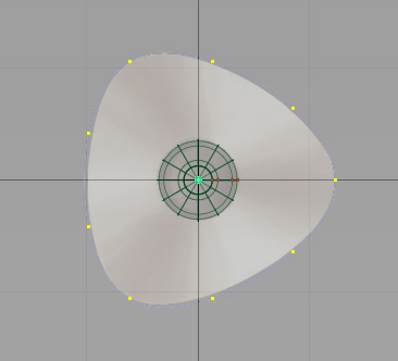
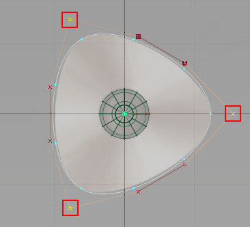
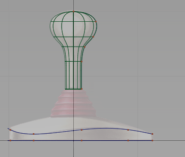
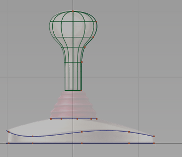
Now select the three CVs which form the apexes of the triangular base.
- Choose Pick > Point Types > CV
 and click the CV nearest the right side of the sketch. Tip:
As the CVs are small, it is sometimes easier to select them by dragging a pick box around each one.
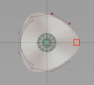
The CV is selected and highlighted in yellow.
- With the Pick > Point Types > CV tool still active, choose the CV at the top left-hand corner of the sketch by clicking and dragging a pick box around it.
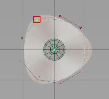
The second CV is selected and highlighted.
- With the Pick > Point Types > CV tool still active, click and drag a pick box around the CV at the bottom left-hand corner of the sketch.
Check that the three CVs are selected and shown in yellow, and that there are two unselected (red) CVs between each corner CV.
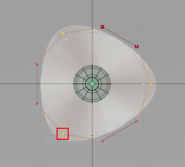
- Choose Transform > Scale.
- Click and drag with the until the outline shape is matched.
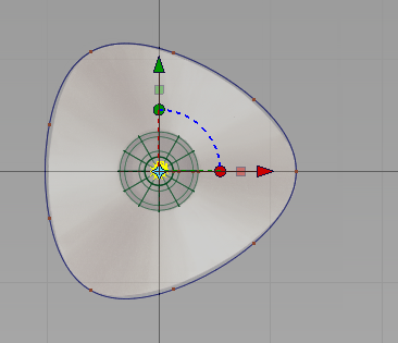
Next, make the CVs and hulls invisible for the curve.
- On the Control Panel, go to the Display section.
Uncheck CV/Hull.
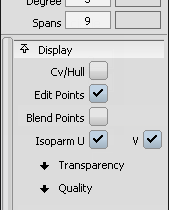
The CVs and Hulls for the curve are no longer visible.
- Choose Pick > Nothing to unpick the curve.
Create the upper curve for the base
Next, create the upper edge of the side wall, by copying and moving the first curve.
- Choose Pick > Object
 and select the base outline curve that you created.
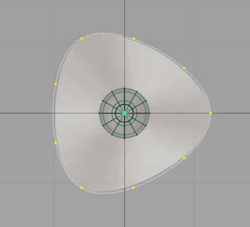
- Choose Edit > Copy
 followed by Edit > Paste
 .
. A second curve is created and placed at the same location as the first. This curve is selected and ready to move.
- Maximize the Left view. Choose Layouts > Left
 or press the F6 hotkey.
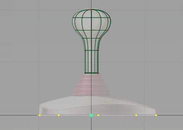
- Choose Transform > Move
 .
. -
Click and drag with the
 upwards to move the curve upwards. Avoid picking the original curve by clicking and dragging away from the selected curve.
 Move the curve so it is aligned with the top of the wavy edge of the joystick base sketch.
- With the curve still selected, click the CV/Hull checkbox in the Control Panel Display section to turn on the CVs and Hulls.

The CVs and hulls appear.
Next, shape the curve in 3D. To be able to see the shape develop, work with all four views on the screen.
- Return to the four views. Use Layouts > All Windows > All Windows
 or the F9 hotkey.
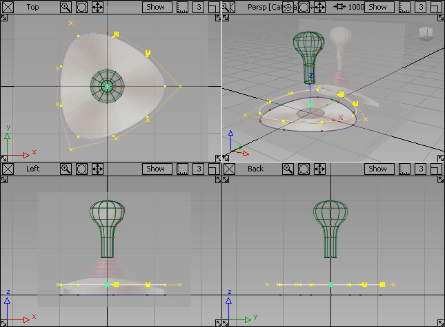
- Choose Pick > Nothing to deselect the curve.
- In the Top view, choose Pick > Point Types > CV and select the three corner CVs.
- Click each CV or drag a pick box over each of them.
Next, move these CV points downwards in the Left view.
- Choose Transform > Move.
-
In the Left view, use the
to move the selected CVs downwards, until the curve matches the shape of the top edge drawn in the sketch. 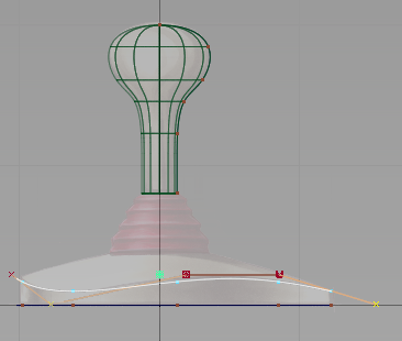
- In the Control Panel, click the CV/Hull checkbox to turn off the CVs.
- Choose Pick > Nothing to deselect the CVs.
Create the top curve for the base
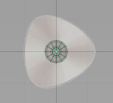
Create the small circle at the top of the base, where the joystick handle is connected.
- Choose Curves > Primitives > Circle.
- Turn on grid snapping by holding down the (Windows) or (Mac) key. In the Top view, click near the origin to place the circle exactly on the center grid point.
A small circle is placed at the origin, with the manipulator shown.
- Scale the circle to match the smaller inner circle on the sketch. Choose Transform > Scale.
Be careful not to click any of the curves, and click and drag outwards with the
. 
Now, move the circle upwards in the Left view.
- With the circle still selected, choose Transform > Move.
- In the Left view, click and drag with the to move the circle upwards to match the top of the base in the sketch.
The circle is now in position at the top of the base.
- On the Control Panel Display section, click the CV/Hull check to turn off the CVs and hulls for the circle.
- Choose Pick > Nothing to deselect the circle.
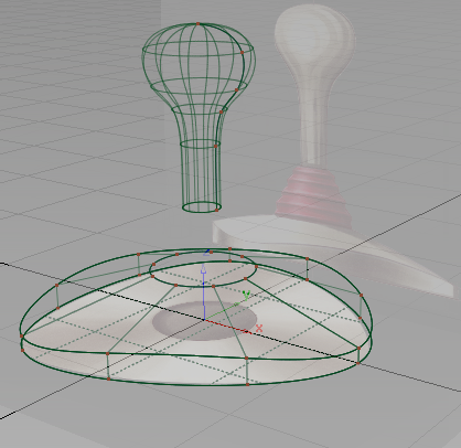
Create the base surfaces
Next, create the surfaces for the base using the Skin and Planar surfaces surface tools. First, create the side wall of the base using a skin surface.
- Maximize the perspective view. Choose Layouts > Perspective
 or F8.
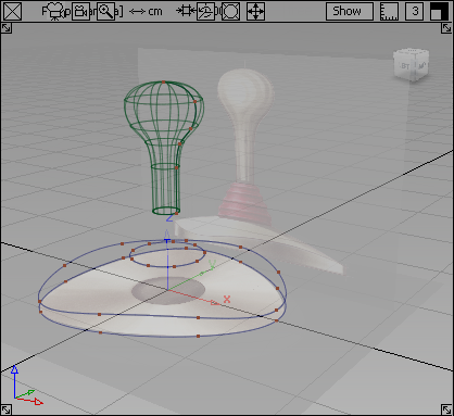
- Choose Surfaces > Skin
 .
. You are prompted to select the first curve.
- Select the first triangular curve you created at the bottom of the base.
- Select the second triangular curve as the top edge of the side wall.
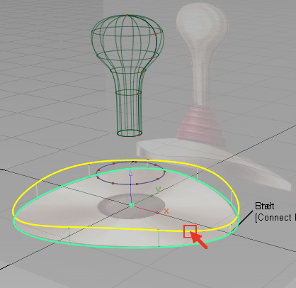
A skin surface is created between the two curves.
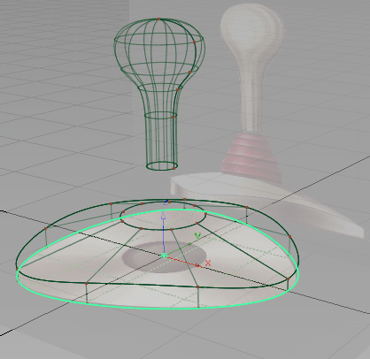
Next, create the surface across the top of the base component.
- Choose Pick > Nothing to unpick the skin surface.
- Surfaces > Skin is automatically selected. Select the second triangular curve again. The pick chooser offers a choice between the curve and the surface you created. Select the circle.
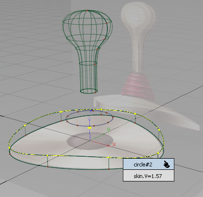
- Now, you are prompted to select the next curve. Click the smaller circle at the top of the base.
The top skin surface is created between the two curves.
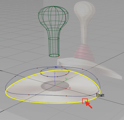
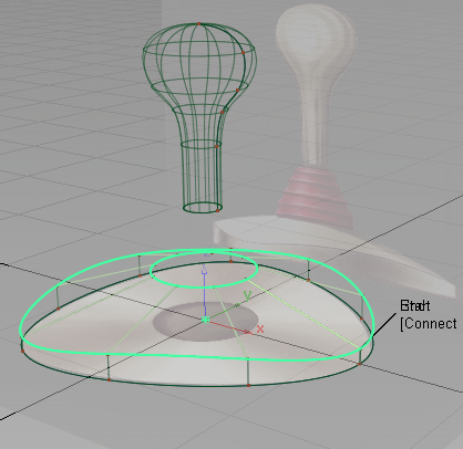
Next, create the surface underneath the base.
- Choose the Surfaces > Planar Surfaces > Set Planar
 tool.
tool. - Select the first triangular curve at the bottom of the base. The pick chooser appears.
Select the circle curve.
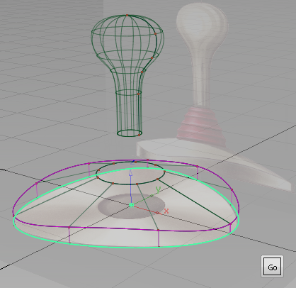
Click the Go button that appears in the bottom right of the screen.
A planar surface is created across the bottom of the base.
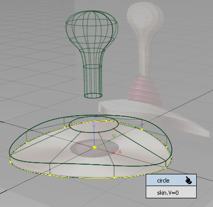
- Choose Pick > Nothing to unpick the planar surface.
Save your work
- Choose File > Save As
 to save the current scene.
 - Save your work in the wire folder of the Lessons project.
- Name your file myjoystick2.wire.