In this section, create grooves to represent styled air intakes.
Open the tutorial file (optional)
If you successfully completed part 4, you can proceed directly to the next step, Create the groove surfaces.
If you were not successful in part 4, open the file called vacuum_Part4.wire, located in the wire folder of the CourseWare project. This file contains the completed model from part 4.
Create the groove surfaces
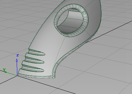
Create the groove surfaces from three extruded tube shapes. The profile of the tubes is circular, and the path follows the general shape of the main body. To create an interesting intersection line, the path curve pulls away from the body shape so the grooves fade out at the outer edge.
To match the character of the main body shape, use the original nozzle curve as a path to extrude the three groove surfaces.
- Choose Pick > Object
 and select the front nozzle curve.
 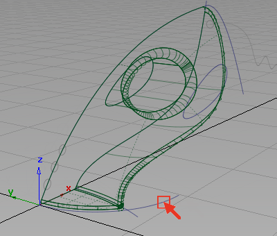 Note:
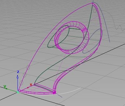
Note:The surfaces are highlighted in pink, indicating that the surfaces have construction history. If you modify the curve, the surfaces updates. You are not modifying the curve; instead, take a copy so you can change the shape without affecting the surfaces.
- Choose Edit > Copy
 followed by Edit > Paste
 to create a copy of the curve.
 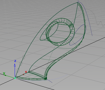 Note:
Note:The surfaces are no longer highlighted in pink, as the new curve is a new copy with no relationship to the surfaces.
- Choose Transform > Scale
 and type 1.75 and press
  (Windows) or
  (Mac) to increase the size of the curve.
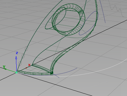
- Choose Pick > Nothing
 to deselect the curve.
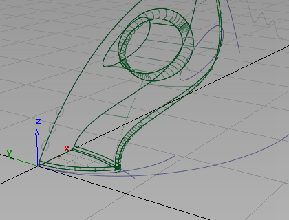
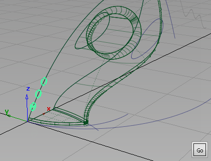
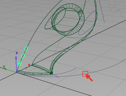
Use this scaled curve as a path curve for the extruded surfaces.
The three circles at the front of the vacuum cleaner have been templated so that you do not accidentally pick or modify them. Now untemplate these circles so you can use them as the generation curves for the extrude surfaces.
- Choose Pick > Template
 and drag a pick box around the three circles.
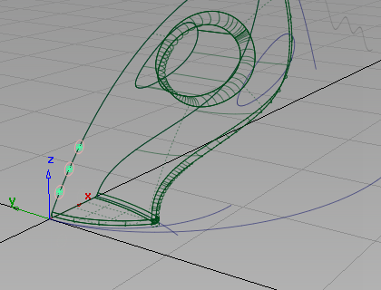
- Choose ObjectDisplay > Template
 to return the curves to pickable geometry.
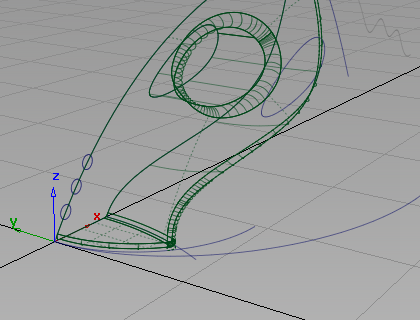
Now extrude the circles along the path curve.
- Choose Surfaces > Swept Surfaces > Extrude
 . You are prompted to select curve(s) to extrude.
 - Pick all three circles.
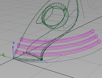
Click Go to select the circles for extrusion.
- You are prompted to select the extrude path. Click the larger curve you have scaled to select it as the path curve.
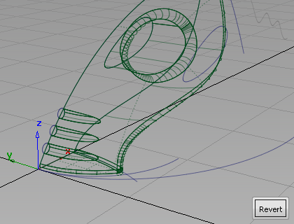
Three surfaces are created, following the shape of the upper surface.

Intersect and Trim the air vents
Now intersect and trim the three extruded surfaces with the upper surface of the vacuum body.
- With the three surfaces still selected, choose Surface Edit > Create CurvesOnSurface > Intersect
 .
. 
The three extruded surfaces are highlighted in pink, indicating they are selected for intersecting.
- Because the three extruded surfaces are already selected, you are prompted to select the surface to intersect.
Pick the upper surface of the vacuum.
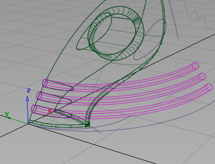
The surfaces are intersected and the curves-on-surface created.
Now trim the excess from the surfaces, starting with the extruded surfaces. In this trimming operation, it is easier to select the part of the surfaces you want to discard, so use the Discard option in the trim tool, instead of the Keep option.
- Choose Pick > Object and drag a pick box to select the three extruded surfaces.
 Tip:
Tip:If you have many surfaces to trim, you can select them all using a pick box before choosing the trim tool.
- Choose Surface Edit > Trim > Trim Surface
 .
. 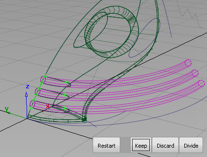
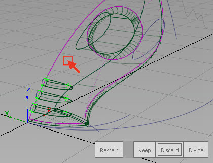
The surfaces are highlighted in pink, and you are prompted to select the regions to trim.
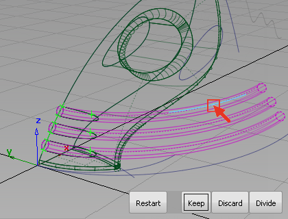
- Click the first extruded surface, in the region to discard
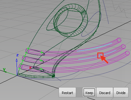
- Pick the second extruded surface, also in the regions to discard.
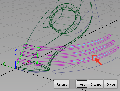
- Pick the third extruded surface, also in the regions to discard.
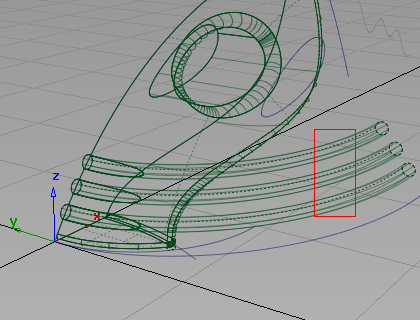
- Click Discard at the lower right corner of the view.
The excess surfaces are discarded.
Next, you trim the upper surface.
- Still in the Trim tool, pick on the upper surface to select it for trimming.
- Click the main region of the upper surface to select it as the part of the surface to keep.
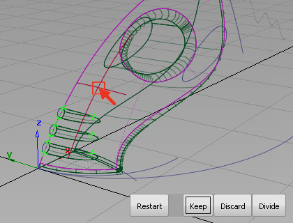
An indicator is placed where you clicked and three buttons appear in the bottom right corner of the view.
- Click Keep to trim the surface.
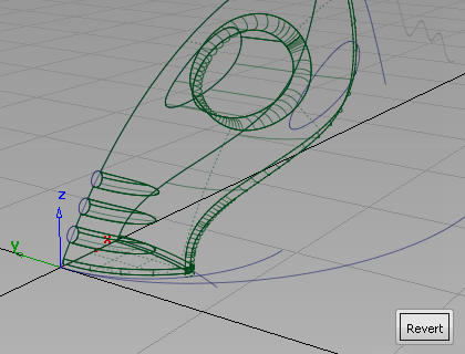
The upper surface is trimmed.
- Choose Pick > Nothing to complete the trimming operation.
Now that you have created all the main surfaces, make the curves layer invisible, so the surfaces can be viewed more clearly.
- On the Layer Bar, click and hold on the curves layer to view the drop-down menu. Select Visible to turn off the visibility of the layer.
On the Layer Bar, the curves layer displays with a dotted outline to indicate that it is turned off.

The curves are no longer displayed on the screen.
- Use diagnostic shading to evaluate the results.
Save your work
- Choose File > Save As
 to save the current scene.
 - Save your work in the wire folder of the Lessons project.
- Name your file myvacuum5.wire.