Previously called Freeform fillet, Freeform Blend enables you to create a transitional surface based on two input contact lines. Those contact lines can be surface curves or free curves.
If a contact line is made up entirely of free curves, that side reverts to G0 Position continuity. As well, Edge align is not possible on that side. If a contact line is made up of both free curves and surface curves, then up to G1 Tangent continuity is allowed on that side. Edge align can be attempted only for the surface curve sections.
Procedures
Freeform Blend Control
- Side 1 Continuity/Side 2 Continuity
-
Choose G0 Position, G1 Tangent, G2 curvature or G3 curvature to determine the type of continuity that will be used between the blend surfaces and primary surfaces. The continuity settings can be specified independently along both sets of boundaries.
G2 curvature continuity means that the curvature (which is the inverse of the radius of curvature) is the same on both sides across the blend surfaces’s boundaries.The V degree of the blend surface is adjusted so that the surface has enough CVs to provide the required continuity on both sides. Degree 4 is needed for G2 continuity on one side, and degree 5 is needed for G2 continuity on both sides
G3 curvature continuity means that the curvature’s rate of change is the same on both sides across the blend surfaces’s boundaries. The V degree of the blend surface is adjusted so that the surface has enough CVs to provide the required continuity on both sides. Degree 6 is needed for G3 continuity on one side, and degree 7 is needed for G3 continuity on both sides.
- Lock Shape Controls
-
When this option is checked on, the values of Side 1 Shape and Side 2 Shape are kept the same.
- Side 1 Shape
-
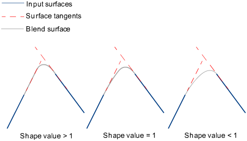
Provides control over the “looseness” or “tightness” of the blend surface toward the first boundary. If the value is greater than 1.0, the result is a blend that fits tighter to the corner of the input surfaces; if the value is less than 1.0, the result is a rounder blend that fits closer to the edge of the first surface.
- Side 2 Shape
-
Provides control over the “looseness” or “tightness” of the blend surface toward the second boundary. If the value is greater than 1.0, the result is a blend that fits tighter to the corner of the input surfaces; if the value is less than 1.0, the result is a rounder blend that fits closer to the edge of the second surface.
- Proportional Crown
- When Side 1 Continuity and Side 2 Continuity are both set to G0 Position, this option lets you add small amounts of crown to the flat blends.
- Crown Value
- When Proportional Crown is checked on, this option controls the height of the crown, and corresponds to a percentage of the distance between the two rails. The slider ranges from -0.25 to 0.25, but larger values can be entered into the field.
G0 blend with: left: no crown; right: crown value = -0.2
- Explicit Control
-
Gives you controls of the surface degree and maximum number of spans in the new blend surface.
Explicit Control Options
These options are only available when Explicit Control is checked.
- U Degree
-
The degree of the new blend surface. Enter a whole number from 2 to 9.
- Max. Spans
-
If Surface Type is set to Multiple surfaces, this value specifies the maximum number of spans for each blend surface. If Surface Type is set to Single surface, it specifies the maximum number of spans inside each pair of boundaries between the original surfaces.
This option is only available when Explicit Control is checked, and Bézier Surfaces is not checked.
Flow Control
- Start/Interior/End
-
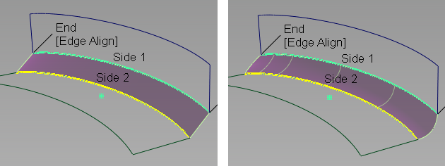
Controls how the blend surface(s) edges (in the V direction) meet up with the edges of the boundary surfaces.
Edge align – The tool tries to colinearly align the blend surfaces’ edges or isoparms (for single surface) to the edges of the boundary surfaces in the V direction.
Connect ends – The edges of the blend surfaces meet the start and/or end points of the boundaries exactly.
Default or Free – The edges of the blend surface(s) (in the V direction) meet the boundaries at a 90 degree angle.
Clicking the labels on the model lets you cycle through all the possible values.
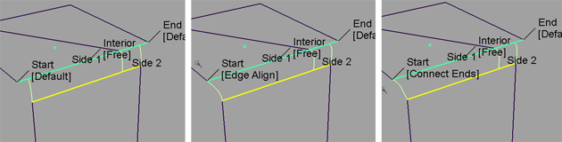
Possible flow control values for Start of blend
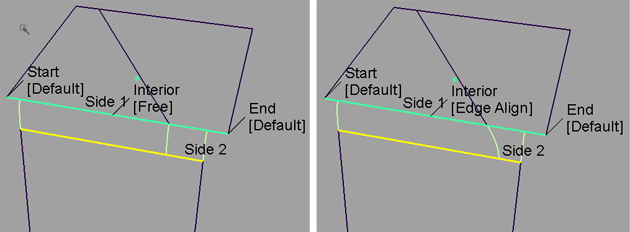
Possible flow control values for Interior of blend
- Modify Range
- When this option is selected, Primary/Secondary Start and End sliders appear in the control window. Unless the Flow Control for the Start and/or End is set to Edge align, these sliders are available, and arrow manipulators appear on the blend surface(s). Drag these arrows to modify the extent of the blend surface(s) across the input surfaces.
- Primary start / Primary end / Secondary start / Secondary end
- Use these sliders to modify the extent of the tangent lines that are used to build the blend. Start and End values of 0.0 and 1.0 respectively, define the original extent.
These are not available if the Flow Control is set to Edge align for either the Start or End.
Surface Structure
- Surface Type
-
If you choose Single surface, a single blend surface is built. If you choose Multiple surfaces, multiple surfaces, corresponding to the boundaries between the original surfaces, are created. (Extra spans are added, if necessary, to meet tangent or curvature requirements.) This gives you much lighter blend surfaces and better continuity with the original surfaces.
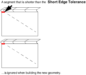
- Short Edge Tolerance
-
In the case of cross-knot insertion, the system will not allow spans of a linear distance less than the Short Edge Tolerance.
- Bézier Surfaces
-
This option only appears if Surface Type is set to Multiple surfaces. If it is checked on, each surface will be a Bézier patch.
Bézier patches have a single span, and their maximum degree in the U direction is set through the Explicit Control section. The default is degree 5.
Control Options
- Auto Update
-
Automatically updates the blend surface as you change options. If the surface to be built is very complex and takes a long time to update, turn this option off and click the Update button when you want to update the surface.
- Continuity Check
-
Displays a manipulator indicating continuity achieved with the existing surfaces along the blend surface edges.
- Chain Select
-
If this box is checked, selecting a boundary input curve also selects all other boundary curves that are tangent continuous with it.