Opens the diagnostic shading control window, which allows you to shade the model using various modes.
Diagnostic Shade
The icons under Shading shade your geometry so you can view and evaluate your surfaces. The various shading modes provide different diagnostic information about surfaces.
Some tools in diagnostic shading, such as Horizontal/Vertical, simulate light reflecting against the surface of your model. Reflecting light on a surface is a good way to check for any bumps, dents, or other irregularities. Reflections also point out any surfaces that do not meet smoothly.
Curvature Evaluation tools color-code the curvature of your surfaces. Color-coding the curvature is useful when, for example, your model will eventually be made in a material that only bends a certain amount before breaking.
Surface Evaluation contains a draft angle map. This diagnostic tool is useful for products produced through injection molding. If the sides of a mold are too steep, an object cannot part with its mold. Draft Angle evaluation shows which parts of an object are in-draft and which are out-of-draft.
In addition, Surface Evaluation includes a way to map mesh deviations. If you have scanned an object, and are trying to match the scan data with your model, mesh deviation lets you know where the two surfaces are not the same.
You can continue to adjust CVs while diagnostic shading is on.
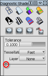
Click the white arrowhead in the lower left corner to show or hide options after selecting a shading mode.
- Tolerance
-
Controls how accurately surfaces are tessellated when Tessellator is Fast. The slider range is 0.0001 to 1.0. The default value is 0.1.
The picture shows a surface with the tolerance slider set to 1. The portions where the shading does not entirely meet the wireframe show the triangulation has been quick but not perfectly accurate. This effect is called “nickeling”. If the slider is set to 0.01, the surfaces of the model become completely shaded because the triangulation is more accurate, however, the process takes longer. Choosing a tolerance value means balancing time versus appearance.
The same tolerance value is found in the option window of WindowDisplay > Hardware Shade
 .
. - Tessellator
-
Fast – Tessellates more quickly and less accurately.
Accurate – Tessellates more accurately and more slowly.
When set to Accurate, a check box is added for Limit Edge Length. If this box is checked, a slider is added for Max. Edge Length. Max. Edge Length is the maximum length (in current units) of a triangle created by tessellation.
The same option is used in the option window of WindowDisplay > Hardware Shade
. - Layer
-
Choose a shader from this menu (Curvature or Horiz/Vert) to layer on top of an already applied diagnostic shader. The default is None.
The parameters of the layered shader appear below the parameters of the original shader in the control window.
Shading Off

The wireframe model appears with no shading. This icon clears the wire model of its current shading. No options are available with this shading mode.
Multi Color
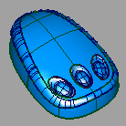
The Multi Color icon shades all the picked surfaces with a single color that you can choose. Use this shading mode to see how your model looks as a finished product, and detect any bumps, dents or other surface irregularities.
You can control the shading qualities with the Light options.
Multi Color options
By default, Diagnostic Shading uses a point light located at the eye position of the camera. You cannot see or pick this light as an object, but you can change its parameters through the following options.
- Show Orientation
-
When this option is checked, components of surfaces or meshes that have reversed normals are shaded in yellow.
(This option is only available in Multi Color mode, and only when Highlights is set to Fast.)
- Color
-
Click the color swatch to set the color, or drag the slider to change the color’s brightness. This option only appears with Multi Color icon selected.
- Specularity
-
Change the size and intensity of highlights on the surface.
- Transparency
-
Set the transparency of the shaded surfaces, from 0.0 (totally opaque) to 1.0 (totally transparent).
- Light Intensity
-
Set the brightness of the light source.
- Highlights
-
When set to Fast, the highlights are calculated more quickly and less accurately. When set to Accurate, the highlights are calculated more accurately, but more slowly.
This option is only available in Multi Color mode.
- Link Light to Camera
-
When this option is checked on (default) the light source for the shading comes from the camera (like a headlight), so that the highlights move over the model as you tumble around it.
Checking off this option un-links the light source from the camera and locks it to its current position, so the highlights remain stationary as you tumble. It also displays two sliders and a manipulator that let you rotate the light around the model. See Move the light around the shaded objects.
Note: The center of rotation is calculated at the moment Link Light to Camera is checked off. It corresponds to the tumble center used when tumbling with Alt + Shift + left mouse button (with Tumble Center set to World Point in View > World Move Camera >Tumble). Setting a point-of-interest (POI) on the geometry or doing a View > Look At modifies the tumble center, hence the center of rotation. - Light Azimuth
- Azimuth values range from -180 degrees to 180 degrees and rotate the light horizontally.
- Light Elevation
- Elevation values range from -90 to 90 degrees and rotate the light vertically.
The following options apply to Multi Color mode only.
- Reflections
-
If this is checked, the following Reflections options are displayed.
- Scene
-
Choose a reflection map by clicking Scene for a drop-down menu. The choices are Showroom, Hall, Evaluation, Diffuse, and Abstract.
Scene imagery by CGI Backgrounds: http://www.cgibackgrounds.com/.
Sky environments images copyright © 2004 Dosch Design GmbH. For more textures, 3D models and HDRIs, please visit http://www.doschdesign.com.
- Reflectivity
-
Use this slider to control how much your model reflects the scene.
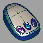
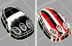
Random Color
The Random color mode shades the surfaces with random colors. As a result, adjacent surfaces show up in different colors, making it easier to see the patch structure, and how the patches align with one another.
Random Color Options
You can control the qualities of the shading with the Random Color options. For the most part, they are the same as the options documented for the Multi Color icon. However, instead of a Color slider, there is a Color saturation slider.
- Color Saturation
-
This slider sets the common saturation, or the “vividness”, of the color.
Curvature Evaluation
This mode includes nine ways to view curvature. The tools color-code the curvature of your surfaces. Color-coding curvature is useful for evaluating the curvature of your model. You can see where the curvature changes either abruptly or subtly. You can also find potential flaws.
Curvature evaluation map options
This mode shows a curvature map.
This option is not available for all Alias products.
Control the type of shading with the following options:
- Curvature Evaluation Type
-
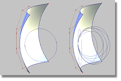
The Curvature Evaluation Type settings listed in the image calculate the curvature of surfaces on each point. This calculation measures the diameter of a circle that touches the surface at each point. Points that have a circle with the same diameter are displayed with the same color. Each point can have several circles. The Curvature Evaluation Type settings specify which circles are used for the calculation.
Choose how to calculate the curvature:
Crv V, Crv U – Display the curvature in the surface’s V or U parameter direction at each point.
Crv Z, Crv Y, Crv X – Display the curvature in the Z, Y, or X direction at each point.
Mean – Use the average of the two principal curvatures to approximate the average curvature through each point.
Gaussian – Use the product of the two principal curvatures.
Princ Min – Use the minimum curvature values (that is, the curvature of the flattest curves that pass through each point).
Princ Max – Use the maximum curvature values (that is, the curvature of the steepest curves that pass through each point).
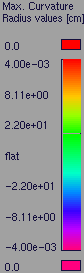
In the image below, the surfaces, or areas of surfaces that fall below the defined radius limit are highlighted in red through the Princ. Max setting.

Crv V, Crv U, Crv Z, Crv Y, Crv X, Mean, Gaussian, Princ Min, and Princ Max types of evaluation
The following options are available for the Crv V, Crv U, Crv Z, Crv Y, Crv X, Mean, Gaussian, Princ Min, and Princ Max surface evaluation types:
- Curvature Color Scale
-
Scales the radius ramp to show finer details of curvature variation.
This option is not available when Min. Radius Limit or Max. Radius Limit are turned on (see below).
- Radius Ramp
-
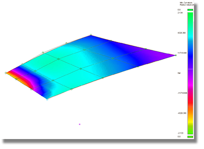
Shows the range of colors that will be applied to the curvature map (and their corresponding curvature radius values) in the active modeling window.
If the +/- band is set to 0.0, the curvature map is relative, and the ramp colors, from left to right, represent increasing curvature values. (The colors are not associated to specific values.)
If you adjust the Curvature Color Scale, Min. Radius Limit or Max Radius Limit, the radius ramp updates interactively.
- Min. Radius Limit
-
Surface regions having a radius less than the Min. Radius Limit value are indicated by one color, and surface regions having a radius greater than the Min. Radius Limit value are indicated by a different color.
This option is only available for the Princ Max evaluation type.
- Max. Radius Limit
-
Surface regions having a radius larger than the Max. Radius Limit value are indicated by one color, and surface regions having a radius less than the Max. Radius Limit value are indicated by a different color.
This option is only available for the Princ Min evaluation type.
- Use bands
- When this option is turned on, the ramp displays solid bands of color instead of slowly varying colors.
This option is not available when Min. Radius Limit or Max. Radius Limit are turned on.
- Transparency
-
Sets the transparency of the shaded surfaces, from 0.0 (totally opaque) to 1.0 (totally transparent).
Iso Angle
Iso Angle highlighting helps you find surface flaws. A common use for Iso Angle is to identify adjacent surfaces with mismatched tangents—in other words, surfaces that do not meet smoothly. You can also use Surface Continuity for this purpose, but Iso Angle gives you a clearer view of the surfaces.
Through a light source manipulator, this mode lets you sweep a single beam across a surface. You can see where the reflected light does not move smoothly. A jump in the reflection indicates flaws in either the surface or its boundary with a second surface.
Multiple beams colored red, black, and white can also be used.
Iso-Angle highlight options
This mode shows iso-angle lines on surfaces to help you visually evaluate continuity across surface boundaries.
- Single, Multiple
-
Controls whether a single black and white iso-angle line is displayed (Single) or multiple colored iso-angle lines are displayed (Multiple).
- Blur
-
The blurriness of iso-angle line edges.
- Transparency
-
The transparency of surfaces with iso-angle lines.
Additional options can be specified through the Evaluate > Iso Angle control window.
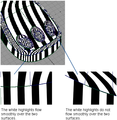
Horizontal/Vertical
This mode shows horizontal or vertical highlights on the surface.
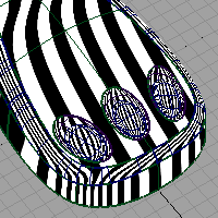
Horizontal/Vertical highlighting helps you find surface flaws. A common use for this is the identification of adjacent surfaces with mismatched tangents—in other words, surfaces that do not meet smoothly. You can also use Surface Continuity for this purpose, but Horizontal/Vertical highlighting gives you a clearer view of the surfaces.
This mode lets you sweep a multiple black and white highlights across a surface. You can see where the highlights do not move smoothly. A jump in the highlight flow indicates flaws in either the surface or its boundary with a second surface.
Horizontal/vertical zebra stripe options
This mode shows horizontal or vertical highlights on the surface.
Highlighting helps you find surface flaws by using a color texture to simulate natural highlights. It maps a color pattern onto a surface based on the angle (from 90 to -90 degrees) at which a viewing ray hits the surface.
A common use for highlighting is to identify adjacent surfaces with mismatched tangents. (You can also use Surface continuity for this, but highlighting gives you a clearer view of the surfaces.) Also note that not all Alias packages include the highlighting features.
- Vert., Horz.
-
Sets the highlights to be vertical or horizontal.
- Lock Texture
-
Normally the highlights are projected from the camera, so the projection changes as you move around the surface. (This is the unlocked mode.) You can turn this option on so that the texture remains locked relative to the surface.
- Repeats
-
Sets the rate at which the texture repeats. Increasing this number will increase the number of highlight lines on the surfaces.
- Transparency
-
Sets the transparency of the shaded surfaces, from 0.0 (totally opaque) to 1.0 (totally transparent).
- Ambient Light
-
Slide to set the level of ambient light, an illumination that comes from all directions and lights all objects uniformly. The slider ranges from 0.0 (no illumination) to 1.0 (maximum illumination).
- Diffuse Light
-
Slide to set the ability of objects to reflect light in all directions. The slider ranges from 0.0 (no light is reflected) to 1.0 (all light is reflected).
- Link Light to Camera
-
When this option is checked on (default) the light source for the shading comes from the camera (like a headlight), so that the highlights move over the model as you tumble around it.
Checking off this option un-links the light source from the camera and locks it to its current position, so the highlights remain stationary as you tumble. It also displays two sliders and a manipulator that let you rotate the light around the model. See Move the light around the shaded objects.
Note: The center of rotation is calculated at the moment Link Light to Camera is checked off. It corresponds to the tumble center used when tumbling with Alt + Shift + left mouse button (with Tumble Center set to World Point in View > World Move Camera >Tumble). Setting a point-of-interest (POI) on the geometry or doing a View > Look At modifies the tumble center, hence the center of rotation. - Light Azimuth
- Azimuth values range from -180 degrees to 180 degrees and rotate the light horizontally.
- Light Elevation
- Elevation values range from -90 to 90 degrees and rotate the light vertically.
Surface Evaluation options
This mode lets you choose between Draft Angle, Deviation Map, or Contact Analysis shading types.
Draft Angle Evaluation
Some manufacturing processes, like injection molding, need you to design molds. A section of a mold only moves in a certain direction during removal. This direction is the pull vector.
Angle-to-pull is the angle between the surface tangent plane at a surface point and the pull vector. When the angle-to-pull is 0 degrees, the pull vector is parallel to the surface tangent plane at that point. When the angle-to-pull is 90 degrees, the pull vector lies normal to the surface.
Most manufacturing processes require that the angle-to-pull for a molded surface be greater than some angle, for example 1 degree, or else the molded part will not separate from the mold. This angle is the draft angle.
When the angle-to-pull is less than the draft angle, the surface point is out-of-draft. When the angle-to-pull is more than the draft angle, the surface point is in-draft.
The Draft Angle shading mode offers the ability to evaluate in-draft and out-of-draft regions along both directions of the pull vector, since a mold often separates in both directions. Positive and negative in-draft and out-of-draft regions of the surface, as well as tolerance regions are shaded different colors. Tolerance regions are "grain wash" zones that forms part of the out-of-draft regions.
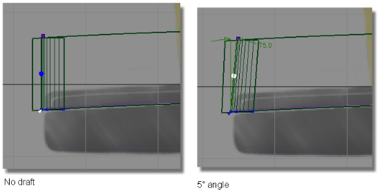
In the pictures above, the draft surface is angled in to the pull direction by 5 degrees. This angle allows the model to be withdrawn from the injection mold.
To gain more functionality, use the Draft Angle setting in Diagnostic Shading in conjunction with the options from the Evaluate > Parting Line tool.
Draft Angle options
These shading options display which parts of a surface are in-draft or out-of-draft for one or both directions of a specified pull vector, and associated draft angle(s). These options appear when you set Type to Draft Angle.
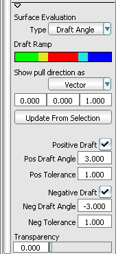
- Draft Ramp
-
In-draft points are shaded blue or green, while out-of-draft points are shaded red. You can also display tolerance regions in cyan and yellow through the Pos Tolerance and Neg Tolerance number fields.
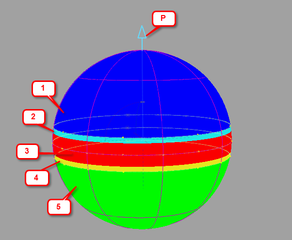
Output from Draft Angle diagnostic shading showing the different shaded regions. P = Pull direction.
- Positive in-draft region
- Positive tolerance region
- Out-of-draft region
- Negative tolerance region
- Negative in-draft region
- Show pull direction as
-
Rotation – Displays values for the X, Y, and Z rotation of a vector that defines the pull direction.
Vector – Displays values for the X, Y, and Z coordinates of a vector that defines the pull direction.
In the three entry fields following Show pull direction as, enter 3D coordinates to define a direction in which the object would be removed from its mold. For example, if you want the pull vector to run along the Z axis, enter 0, 0, 1.
- Update From Selection
-
Click this button to set the pull direction to be that of an already selected (picked) vector or plane. In the case of a plane, the direction perpendicular to the plane is used.
The X, Y, Z fields are automatically set to the coordinates of the picked vector.
- Positive Draft
- Check on this option if you want to see the in-draft and out-of-draft regions for a given draft angle (Pos Draft Angle) with respect to the given pull vector.
- Pos Draft Angle
-
If the angle between a surface point and the pull vector is less than this value, the surface point is out-of-draft, and is colored red.
If the angle between a surface point and the pull vector is more than this value, the surface point is in-draft, and is colored blue.
- Pos Tolerance
- Displays a cyan tolerance region between the positive in-draft and out-of-draft regions. The tolerance value represents an angle measured in degrees. If the tolerance value is 0, no tolerance region is displayed.
- Negative Draft
- Check on this option if you want to see the in-draft and out-of-draft regions for a given draft angle (Neg Draft Angle) with respect to the negative (opposite) direction of the pull vector.
- Neg Draft Angle
-
If the angle between a surface point and the direction opposite to the pull vector is less than this value, the surface point is out-of-draft, and is colored red.
If the angle between a surface point and the direction opposite to the pull vector is more than this value, the surface point is in-draft, and is colored green.
- Neg Tolerance
- Displays a yellow tolerance region between the negative in-draft and out-of-draft regions. The tolerance value represents an angle measured in degrees. If the tolerance value is 0, no tolerance region is displayed.
- Transparency
-
Sets the transparency of the shaded surfaces, from 0.0 (totally opaque) to 1.0 (totally transparent).
Deviation Map Evaluation
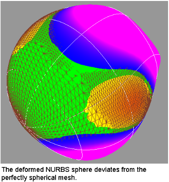
If you have scanned an object, and are trying to match the scan data with your NURBS surfaces, the Deviation Map mode lets you know where the two objects deviate. It calculates the distance between a set of meshes and a set of NURBS surfaces, and displays it as a color-coded map, for a quick assessment of the gap’s severity.
Deviation Map can also show the deviation between two sets of surfaces, or two sets of meshes.
This mode acts as a toggle. It only displays the shading once it has been calculated once through the use of Evaluate > Deviation Map![]() .
.
See also Visualize the deviation between mesh-surface, surface-surface or mesh-mesh
Deviation Map options
These options appear when you select Deviation Map through the drop-down menu for the Type button.
- Transparency
-
Sets the transparency of the shaded surfaces or meshes, from 0.0 (totally opaque) to 1.0 (totally transparent).
Contact Analysis Evaluation
This type of surface evaluation provides you with an ability to analyse the safety of a model. It is especially useful with car interior surface design work.
Equally capable of working with meshes and NURBS surfaces, this shading mode enables you to examine a collection of surfaces for potential impact points with a head (represented by a sphere).
The tool internally creates a sphere, to judge where the head could contact the surface model. For example, some spaces, like between the steering wheel and the dash board, are too small for the head to fit into. Only the areas where a head can actually fit in the case of an accident are examined for sharpness and safety issues.
Before analyzing the model, ensure that normals are unified. If they point in different directions, results will be unreliable.
This mode acts as a toggle. It only displays the shading once it has been calculated once through the use of Evaluate > Contact Analysis![]() .
.
User-defined texture options
This mode shows a user-defined texture reflected on the picked surfaces. You can use one of the two default textures, or load one of your own.
- Map Type
-
Showroom – Shows a texture map with a showroom reflection.
Photo-Horizon – Shows a texture map with a photo-horizon reflection. The abstract Photo-Horizon ramp produces a high contrast effect often used in stylized sketching.
Diffuse – Shows a texture map with a diffuse reflection. The abstract Diffuse ramp provides low contrast reflections appropriate for studying overall form and volumes.
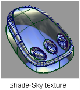
Shade-Sky – Shows a texture map with the reflection of the sky.
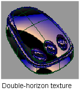
Double-horizon – Uses two reflective highlights, as though the model was reflecting a double-horizon.
User defined – Choose your own reflected texture.
- Change texture to
-
Enter the name of a texture file to use instead of the default horizon or sky texture. You can use Alias PIX, SGI’s RGB, TIF and various other image file formats. (The GIF and JPEG file formats are not supported.)
Click the arrow button to choose the texture from a file requester.
- Lock Texture
-
Normally the highlights are projected from the camera, so the projection changes as you move around the surface. (This is the unlocked mode.) You can turn this option on so that the texture remains locked relative to the surface.
- Repeats
-
Sets the rate at which the texture repeats. Increasing this number will increase the number of highlight lines on the surfaces.
- Transparency
-
Sets the transparency of the shaded surfaces, from 0.0 (totally opaque) to 1.0 (totally transparent).
- Ambient Light
-
Slide to set the level of ambient light, an illumination that comes from all directions and lights all objects uniformly. The slider ranges from 0.0 (no illumination) to 1.0 (maximum illumination).
- Diffuse Light
-
Slide to set the ability of objects to reflect light in all directions. The slider ranges from 0.0 (no light is reflected) to 1.0 (all light is reflected).
- Link Light to Camera
-
When this option is checked on (default) the light source for the shading comes from the camera (like a headlight), so that the highlights move over the model as you tumble around it.
Checking off this option un-links the light source from the camera and locks it to its current position, so the highlights remain stationary as you tumble. It also displays two sliders and a manipulator that let you rotate the light around the model. See Move the light around the shaded objects.
Note: The center of rotation is calculated at the moment Link Light to Camera is checked off. It corresponds to the tumble center used when tumbling with Alt + Shift + left mouse button (with Tumble Center set to World Point in View > World Move Camera >Tumble). Setting a point-of-interest (POI) on the geometry or doing a View > Look At modifies the tumble center, hence the center of rotation. - Light Azimuth
- Azimuth values range from -180 degrees to 180 degrees and rotate the light horizontally.
- Light Elevation
- Elevation values range from -90 to 90 degrees and rotate the light vertically.
Visual States
Click one of the three Visual State buttons to turn on hardware shading and shade the model using the environment and shading settings associated with the button.
You can change the settings associated with each of these buttons by clicking the button preset you want to change and using the Visual State options. The settings for the three Visual State buttons are stored with your user preferences.
Visual State Options
- Shade Settings
-
Click this button to adjust the hardware shading settings in the Hardware Shade dialog box.
- Environment Editor
-
Click this button to adjust the environment settings in the Environment Editor.
- Save To Prefs
-
Click this button to save your changes to your user preferences.
File State
The settings for the last active environment are stored with the File State button when you save your file. The settings are saved with the file, so anyone opening the file can set the environment to your last active environment using this button.
You can change the settings associated with the File State button by clicking the button and using the File State options. Save the file to save the new settings with the button.
File State Options
- Shade Settings
-
Click this button to adjust the hardware shading settings in the Hardware Shade dialog box.
- Environment Editor
-
Click this button to adjust the environment settings in the Environment Editor.