Creates a transition surface between two surfaces or sets of surfaces.
Procedures
Choose the type of a fillet surface
Control the radius along the length of a variable fillet surface
Manipulate fillet surface cross section and continuity
Surface Fillet Control options
- Construction Type
-
This pop-up menu controls the type of fillet.
Radius – Produces a rolling-ball fillet, where you control the radius value(s) at the center of the fillet or the position of the tangent lines (but not the width of the fillet).
Chord – Lets you control the distance between the two edges of the fillet, instead of the radius. Use the Chordal Length (or Tangent Length) option to set the distance to maintain.
- Section Type
-
This menu controls the shape of the fillet’s cross-section by imposing different continuity levels with the input surfaces on each side.
G0 Chamfer – Creates a chamfer edge between the two sets of surfaces. This type maintains only position continuity with the surfaces on either side.
G1 Circular – Creates a fillet with circular cross-section, tangent to both sets of surfaces. This type maintains tangent continuity with the surfaces on either side.
G2 Curvature – Maintains curvature continuity (G2) with both sets of surfaces. G2 continuity means that the curvature (which is the inverse of the radius of curvature) is the same on both sides across the fillet’s boundaries.
G3 Curvature – Maintains G3 continuity with both sets of surfaces. G3 continuity means that the curvature’s rate of change is the same on both sides across the fillet’s boundaries.
When calculating the fillet, the V degree is adjusted so that the surface has enough CVs to provide the required continuity on both sides. Degree 5 is needed for G2 Curvature and degree 7 is needed for G3 Curvature.
Bias – Creates a fillet with a peak radius and tangent offset, the center of which is biased toward (closer to) one set of surfaces.
Lead – Creates a fillet with a peak radius and tangent offset that define the point of contact with the input surfaces. This type maintains tangent continuity with the surfaces on either side.
- Bias Factor
-
Moves the center rail of the fillet surface closer to one side. A value of 0 is centered. Negative values bias toward the first set of surfaces. Positive values bias toward the second set of surfaces.
This option is only available when Section Type is Bias.
- Curvature
-
This option is only available when the Section Type option is set to Bias , G2 Curvature or G3 Curvature.
None – Do not maintain curvature continuity.
Side 1, Side 2 – Make the fillet surface curvature continuous with the first or second set of surfaces.
Both: Make the fillet surface curvature continuous with both sets of surfaces.
- Variable Fillets
-
If this option is checked, you can set the radius or chordal length/tangent length at different points along the length of the fillet.
Radius, distance, and surface controls
- Specify
-
This option and its related parameters are only visible if Construction Type is Radius.
For Bias and Lead section types, choose whether you want to specify the Peak Radius or the Knee Ratio.
For G1 Circular, G2 Curvature, and G3 Curvature section types, choose whether you want to specify the Center Radius, the Tangent Offset, or Both. Those values offer different ways of specifying the peak/center radius and/or lead distance.
Note: The lead distance expresses how much a fillet extends into the adjacent slab surfaces. A longer lead distance provides a smoother transition and better continuity.If Specify is set to Center radius or Tangent offset, and you also set the Form Factor, the third parameter (either Tangent offset or Center radius) varies along the fillet. Both lets you specify both the Tangent Offset and Center Radius of the fillet, but not the Form Factor. The form factor is calculated automatically from these two values and varies along the fillet.
- Default Profile Radius/Center Radius/Peak Radius
-
The Peak Radius slider appears only when Section Type is Bias or Lead, and Specify is set to Peak Radius. The peak radius is the minimum radius that the fillet is allowed to have at the top.
The Center Radius slider appears only when Section Type is G1 Circular, G2 Curvature, or G3 Curvature, and Specify is set to Center Radius. The center radius is the radius at the arclength center of the fillet.
If Variable Fillets is checked on, the Specify option becomes unavailable. You can only specify tangent offsets, not center radii.
- Tangent Offset/Default Tangent Offset
-
Radius of a sphere that is tangent to both input surfaces at the endpoints (that is, contact points) of a given U-isoparm on the fillet.
When Variable Fillets is checked on, Default Tangent Offset is the initial tangent offset along the whole length of the fillet. You then add manipulators at various points along the fillet and specify different tangent offset values.
This option is only available when Construction Type is Radius.
- Knee Ratio
-
This is the ratio between Peak Radius and Tangent Offset, that is Knee Ratio = Peak Radius / Tangent Offset.
It is only available when Section Type is Bias or Lead.
- Form Factor
-
This parameter lets you adjust the shape of the fillet. It specifies the ratio between the lengths of the innermost and outermost CV arms of the hull in the V direction of the fillet. Values range from 0.1 to 2.0. The smaller the value, the sharper the bend in the fillet.
This option is only available when Section Type is G1 Circular, G2 Curvature, or G3 Curvature.
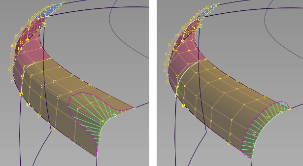
A G2 fillet with, left: form factor = 0.1, and right: form factor = 2.0.
- Chordal Type
-
Chordal length – a chordal length is specified in the field below.
Tangent length – a tangent length is specified in the field below.
This option is only available when Construction Type is Chord.
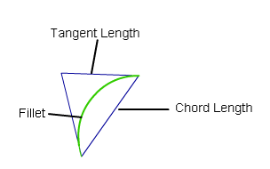
- Chordal Length/Tangent Length
-
The distance to maintain between the two sides of the fillet, or the length of the tangent segment (see picture above).
This option is only available when Construction Type is Chord.
- Explicit Control
-
Gives you controls of the surface degree(s) and maximum number of spans in the new fillet surface.
Explicit Control Options
These options are only available when Explicit Control is turned on.
- (Length) U Degree
-
The degree of the new fillet surface in the U direction (that is, along the surface edges). Enter a whole number from 2 to 9.
- (Section) V Degree
-
The degree of the new fillet surface in the V direction (that is, from one rail to the other).
This option is only available when Section Type is set to G1 Circular (values range from 3 to 6) or G2 Curvature (values range from 5 to 7).
Note: G3 Curvature does not provide a V Degree slider, but keeps the V degree set to 7 as required by G3 transitions. - Max. Spans
-
If Surface Type is set to Multiple surfaces, this value specifies the maximum number of spans for each fillet surface. If Surface Type is set to Single surface, it specifies the maximum number of spans inside each pair of boundaries between the original surfaces.
This option is only available when Explicit Control is checked, and neither Bezier Surfaces nor Uniform Spans is checked.
- Uniform Spans
- When this option is checked on, a Spans field appears that lets you specify the exact number of spans of equal length for each fillet surface. If Bezier Surfaces is also on, then a corresponding number of Bézier patches of equal lengths is created.
Flow Control
- Start/Interior/End
-
Controls how the fillet surface(s) edges (in the V direction) meet up with the edges of the boundary surfaces.
Edge align – The tool tries to colinearly align the fillet surfaces’ edges or isoparms (for single surface) to the edges of the boundary surfaces in the V direction.
Extend – The fillet is extended so that it reaches to the end of the longest boundary surface, at its start and/or end.
Default or Free – The edges (in the V direction) of the fillet meet the boundaries at a 90 degree angle.
Clicking the labels on the model lets you cycle through all the possible values.
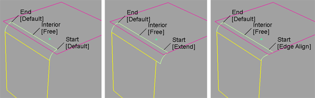
Possible flow control values for Start of fillet
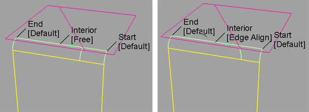
Possible flow control values for Interior of fillet
- Modify Range
-
When this option is selected, Start and End sliders appear in the control window, and arrow manipulators appear on the selected fillets. Drag these arrows to modify the extent of the fillets across the input surfaces.
Note: The Start or End of the range can only be modified if the flow control option for that end was set to Default. - Start/End
-
Use these sliders to modify the extent of the fillet. Start and End values of 0.0 and 1.0 respectively, define the original extent.
Fillet Structure
- Surface Type
-
Multiple surfaces – Multiple surfaces, corresponding to the boundaries between the original surfaces, are created. (Extra spans are added if necessary, and subject to Max. Spans, to meet tangent or curvature requirements.) This gives you much lighter fillet surfaces and better continuity with the original surfaces.
Single surface – A single fillet surface is built.
If curves-on-surface are created at the edges of the fillets (see Trim Type option below) they are segmented to correspond to the multiple fillet surfaces.
- Bézier Surfaces
-
This option only appears if Surface Type is set to Multiple surfaces. If it is checked on, each surface will be a Bézier patch.
Bézier patches have a single span, and their maximum degree in the U direction is set through the Explicit Control section. The default is degree 5.
- Short Edge Tolerance
-
In the case of cross-knot insertion, the system will not allow spans to have a length smaller than this value.
Control Options
- Trim Type
-
Automatic – Automatically trims the original surfaces back to the contact line.
Curves-on-surface– Creates curves on surface along the contact lines, allowing you to trim manually.
Off – Does not trim the original surfaces.
- Auto Update
-
Automatically updates the fillet surface as you change options.
If your surface is very complex and takes a long time to update, turn this option off and click the Update button when you want to update the surface.
Tip:The
 key can be used to interrupt lengthy surface fillet computations.
 - Curvature Comb
-
Displays a curvature comb plot across the resulting surface.
- Continuity Check
-
Displays a manipulator indicating continuity achieved with the existing surfaces along the fillet edges.
This option is only available when Trim Type is Curves-on-surface or Automatic.
Buttons
- Reset
-
Restores your saved settings. If you have not saved custom options, Reset restores the installed option settings.
- Update
-
Updates the surface with the current settings when Auto Update is off.
- Undo All
-
Reverses any effects of the tool.
- Next
-
Resets the tool to begin a new surface.