Assembly constraints and assembly joints both create relationships that determine component placement and allowable movement.
The Constrain and Assemble commands are legacy methods of positioning components and gradually eliminating degrees of freedom (DOF) using constraints.
The Joint command reduces the complexity of component relationships. Use Joint to position a component and fully define the motion. You can use Lock and Protect controls with Joint. These options are available in the context menu when you select a connection in the browser. Lock eliminates all degrees of freedom, but allows the component to change location when related components move. Grounding also eliminates all degrees of freedom but it fixes the component position in space. To warn if added relationships violate the required motion, use Protect on a joint.
You can specify an allowable range of motion limits for both constraint and connect relationships.
Getting started positioning components
- In older releases of Inventor, the first part you placed in an assembly was grounded. Its position was fixed, with the part origin coincident with the assembly origin. It is good practice to ground at least one component that does not move to provide an anchor for other components. To ground the required component, use the context menu when you place the component and select Place Grounded at Origin.
- When you place a component in the assembly, use the context menu to rotate about X, Y, or Z to establish the initial orientation.
Assembly joint
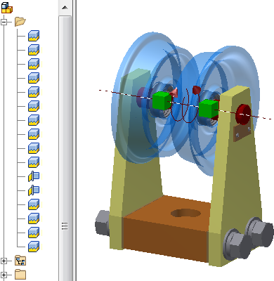
In the following image, two assembly joint types, Rigid and Rotational, are used to locate the components and define degrees of freedom. Because Joint explicitly defines the component location and degrees of freedom, fewer connections are required to provide consistent and predictable results. Notice that Rigid is the most common joint type and only the two bearings rotate. In other words, the assembly motion of all components is defined correctly. You can use joints with constraints to obtain the required results.

Assembly constrain
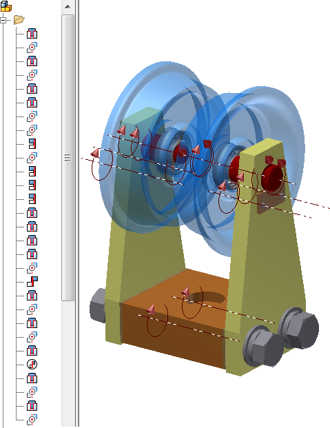
In the following image, the constraints Mate, Flush, and Insert are used to locate components and define the range of motion. Constraints typically require more relationships than connect to define degrees of freedom and position components. Notice that the fasteners in the following image still have rotational freedom. If orientation is not critical, extra degrees of freedom are common when you use constraints . You can use constraints with joints to obtain the required results.

Create assembly relationships
Joint command
Joint can automatically determine the connection type based on origin selections. You can also select a joint type, and then select the objects to position and join. In addition to creating the relationship, you can change the browser name and apply limits.
Joint moves the first selected component to the second selection. If necessary, existing relationships or grounded status are relaxed to allow the first component to move. To help you position components correctly, the joint previews the effects before it is applied.
Constrain command
You select a constraint type to update the Place Constraint dialog box then select the objects to constrain. In addition to creating the constraint, you can change the browser name and apply limits.
To help you position components correctly, you can preview the effects of a constraint before it is applied. After you select the constraint type, the two components, and set the angle or offset, the components move into the constrained position. You can adjust settings as needed, and then apply them.
Assemble command
You select the objects to constrain, and then select the type of constraint to apply. A mini toolbar displays in the graphics window instead of a dialog box. Assemble automatically selects valid constraint types based on your geometry selections. For example, if you select planar faces only the Mate-Mate, Mate-Flush, and Angle-Directed constraint types are displayed in the list. If your first selection is a circular edge, only the Insert-Opposed and Insert-Aligned constraints are listed, and your second selection is limited to a circular edge.
The Assemble command always moves the first selected component to the second selection. If necessary, existing constraints or grounded status are relaxed to allow the first component to move. When you exit the Assemble command, all new and existing constraints are calculated. If there is a conflict, the Assemble Constraint Management dialog displays so you can suppress or delete the constraints. Use this workflow to change the location of a component when you are unsure how it was constrained. You can reposition the component and then resolve any constraint conflicts.
Some constraint types (Motion, Translation, Angle-Undirected, and Angle-Explicit Reference Vector) are not supported in the Assemble command. Also, you cannot change the constraint name or apply limits. You can edit the constraint after it is created to change those settings.
Positional limits
Limits are specified values that define the allowable range of motion for components that move or rotate. Both Constrain and Joint support limits. A relationship with limits is identified in the browser by a +/- symbol.
Simulating the motion of moving parts
If you are designing a mechanism with moving parts, simulating the motion is a key component of the prototyping process. Before deciding on the appropriate method, consider the following:
- Use limits on constraints or joints to define the range of allowable movement or rotation.
- Motion constraints use defined rotational or rotational-translational ratios to depict movement between components. Use motion constraints for a lightweight method to verify movement such as the proper gear ratio.
- Contact Sets use physical contact between components to limit movement. If interference is detected, the components do not move. This method requires more computation than a motion constraint.
- Dynamic simulation uses physical properties like mass, friction, inertia matrix, and load definition to provide information on how the components act in the physical world. Use the Inventor Simulation Suite to study the influence and result of actual forces on your design. This method requires the most computation but provides the most accurate results. A link to Inventor Studio enables realistic animation recording of the motion.
- Inventor Studio enables animation of assembly relationships and positional representations to create mechanistic motion. Image and video output of realistic or illustrative content is the main use for Inventor Studio.
Layout constraint
Layout constraints are created when you execute Make Components. Layout constraints define the relationship between the layout and parts push derived from the layout. The Layout constraint comprises flush constraints between the three primary planes of the layout and derived parts, and a zero degree angle constraint between the Z axes of the layout and derived parts.
- Constrain to Layout Plane - constrains the component to the layout plane, at a fixed offset, and allows component movement parallel to the layout plane. If not selected, your component can move perpendicular to the layout plane (along the Z axis of the layout part).
- Layout Controls Position - your layout part controls the X and Y position of the assembly component.
- Assembly Controls Position - you can move the component relative to its constraints and degrees of freedom. You can constrain this motion to 2D or 3D.
Layout constraints provide certain behaviors that are useful in skeletal modeling:
The default behaviors for layout constraints are initialized based on your sketch constraint relationships and options you select during Make Components. To changes behaviors for a component, right-click the component instance in the browser, select Layout Constraint in the context menu, and choose the appropriate position options.
You can modify layout constraints to achieve the target behavior. However, you cannot place new layout constraints except by the Make Components workflow.
Retained constraints on replaced components
There are two ways to retain constraints for replaced components:
- Create the existing and replacement component from a common base (by using Save Copy As option).
- Use iMates.
iMates are constraint pairs in parts that define how a part fits together with other components each time it is placed in an assembly.
Convert existing assembly constraints to iMate definitions by right-clicking the component in the browser, and then selecting Infer iMates. You can also create iMates as you edit or modify a component.
Strategy for creating relationships in complex assemblies
To simplify positioning the members of a complex assembly, create several small assemblies; apply relationships as needed, then save each one as a separate file. This approach allows the subassembly to be positioned in upstream assemblies as a single unit.
Grouping parts in subassemblies also simplifies the process of using the parts in more than one assembly.