Creates a feature or body by revolving one or more sketched profiles around an axis. Except for surfaces, profiles must be closed loops.
Access
Ribbon:
Model tab
 Create panel
 Revolve
![]()
Ribbon:
Model tab
 Primitives panel
 Sphere

Ribbon:
Model tab
 Primitives panel
 Torus
Torus

Shape
- Profile
-
Selects a profile to revolve. If there are multiple profiles and none are selected, click Profile, and then click one or more profiles in the graphics window. Press Ctrl, and then click to remove a profile from the selection set.
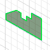
 Single Profile Automatically selects a profile.
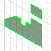
  Multiple Profiles Selects multiple profiles from same sketch plane. Selections are highlighted.
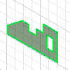
  Nested Profiles Selects multiple nested profiles. The result of revolving an interior loop is opposite the result of revolving an exterior loop. For example, revolved concentric circles form a hollow torus.
 - Axis
-
Selects the axis of revolution. The axis can be a work axis, a construction line, or a normal line.
- Solids
-
Selects the participating solid body in a multi-body part.
Output
- Solid
-
Creates a solid feature from an open or closed profile. Open profile is not available for base features or primitives.
- Surface
-
Creates a surface feature from an open or closed profile. Can be used as a construction surface on which other features terminate or used as a split tool to create a split part. Not available in the assembly environment.
Operation
Specifies whether the revolution joins, cuts, or intersects with another feature. Not available for base features but required for all other features.
 Join
Join -
Adds the volume created by the revolved feature to another feature or body. Not available in the assembly environment.
 Cut
Cut -
Removes the volume created by the revolved feature from another feature or body.
 Intersect
 -
Creates a feature from the shared volume of the revolved feature and another feature or body. Material not included in the shared volume is deleted. Not available in the assembly environment.
 New solid
 -
Creates a new solid body. Each solid body is an independent collection of features separate from other bodies. A body can share features with other bodies.
Extents
Determines the method for the revolution and sets the angular displacement of the profile around a centerline. Click the arrow to list the extent methods, select one, and then enter a value. Revolutions can be a specific distance or can terminate on a work plane or part face.
- Angle
-
Revolves the profile through the specified angle. Direction arrows specify direction of revolution.
- Angle - Angle
-
Angle - Angle Accepts two different angular values to revolve the profile in two directions - one positive and one negative. Click Asymmetric to activate and enter the second angular displacement value.
Direction arrows reverse the two angular displacements so that the positive angle becomes negative and the negative angle becomes positive.
- Full
-
Revolves the profile 360 degrees.
- To
-
Terminates the revolved feature on the selected face or plane, or on a face that extends beyond the termination plane.
For assembly revolved features, faces and planes that reside on other components can be selected. The selected faces or planes must reside on the same assembly level as the assembly revolution being created.
- Between
-
Selects beginning and ending faces or planes on which to terminate the revolution.
For assembly revolved features, faces and planes that reside on other components can be selected. The selected faces or planes must reside on the same assembly level as the assembly revolution being created.
- To - Next
-
To - Next Selects the next possible face or plane on which to terminate the revolution in the specified direction. Dragging the profile flips the revolution to either side of the sketch plane.
To - Next Not available for base features or assembly revolutions.
Tip: For To Next, click the body to end the feature creation.
Match Shape
Selects the type of shape propagation: Match Contour or Match Shape. This option is available in the part environment when you select an open profile.

Match Shape Select the Match Shape option to create a flood-fill revolved feature. The open ends of the profile are extended to the axis of revolution (if possible), or to the bounding box of the body. The Match Shape revolution generates a stable and predictable body for topology changes on the defining faces.

Match ContourClear the Match Shape option to close the open profile by extending the open ends to the part, and closing the gap between them. The extrusion is created as if you specified the closed profile.
Infer iMate
Select the check box to place an iMate automatically on a full circular edge. Autodesk Inventor attempts to place the iMate on the closed loop most likely to be useful. In most cases, place only one or two iMates per part.