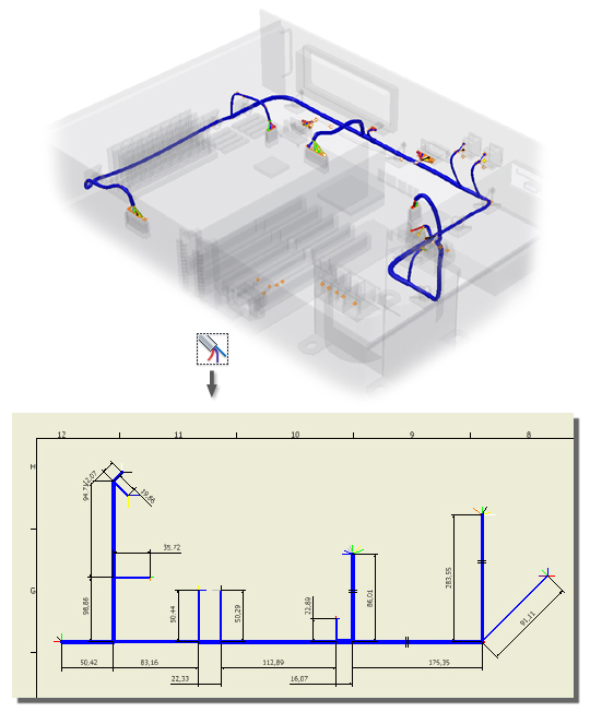
In the nailboard environment you create a 2D flattened view of the harness in a drawing. The nailboard drawing is created for the manufacture of a wire harness, cable, or ribbon cable. All harness wires, cables, and segments are drawn as straight lines. Ribbon cables are drawn as rectangles. The nailboard varies in complexity and detail according to your company standards. Along with the 2D view, the drawing often contains a bill of materials, wire list, images of connectors, dimensions, pin numbers, and other attribute data.

The 3D harness shape can be rearranged, but the length of the harness is preserved. The work points defined in 3D translate to 2D points that can be used for manipulation or for dimensioning. The relative positions of the work points from 3D to 2D are maintained, including the distance between any two points.
What is displayed in the nailboard drawing by default?
- The active harness in a sketch in the drawing draft view.
- The custom title block and border.
- Segments that contain wires or cables. Segment endpoints. Internal segment points are hidden until the segment is selected. Segments with looms attached are displayed with the loom appearance.
- Routed and unrouted wires and cable wires and any internal wire points.
- Ribbon cables including conductor one, any folds, and any internal points.
- Labels on wire or cable wire pins or segment work points are displayed as text boxes centered on the associated pin or point. Once label is moved, it is displayed with a leader line to the workpoint.
- Dangling wires and cable wires. Segments with dangling wires include the dangling wires so the segment width is correct on the drawing.
- If both ends of the wire are dangling, the wire does not appear in the graphics window, but is listed in the browser.
- Pins to which the wires are attached. Both routed and unrouted wires are in the drawing, but only segments that contain wires and/or cables are shown.
- Splices with wires attached.
How do nailboard drawings differ from standard Autodesk Inventor drawings?
- Nailboards use Draft views as the default view where the specialized nailboard sketch is located. Additional base views of connectors can be added to the sheet.
- Nailboard dimensions and geometry represent the wire, segment, and ribbon cable adjusted length values.
- The Break Sketch Entity removes the length of wire or segment you specify. You can delete the symbol and move it along the line or segment.
- Only looms and labels are represented in the drawing view, other virtual parts are not.
When do updates occur?
Changes made to part and assembly models that affect associated nailboard drawings are updated each time the nailboard drawing is opened. The nailboard drawing also updates when the nailboard is activated for editing, while in the nailboard sketch.
To keep a nailboard drawing static until it is updated manually, use Defer Updates. To force an update, clear the Defer Update check box.
How are loops represented in nailboard drawings?
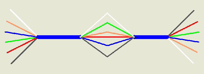
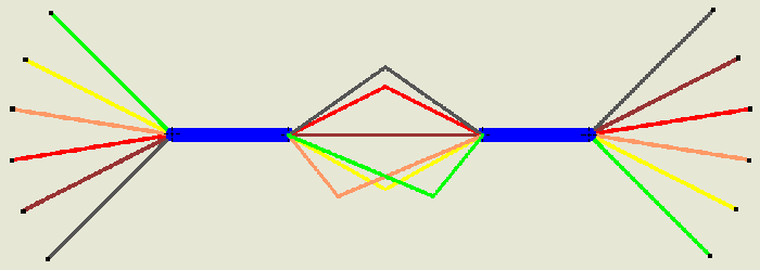
There are two different types of loops that can occur in a harness, wire loops and nested segment loops. These loops are represented differently in the nailboard drawings.
The loop is represented as:
Straight lines - if the exposed wire pieces are of equal length and have no work points.

V-shaped lines of equal lengths - if the exposed wire pieces are of equal length and have work points.

V-shaped lines of different lengths - if the exposed wire pieces are of different lengths.

A mixture of V-shaped lines of varying and equal lengths - if the exposed wire pieces are of both equal and different lengths.

A mixture of V-shaped lines and straight segments - if the harness contains nested segments and exposed wire pieces of equal and different lengths.

How are wires terminated at the same pin (multi-terminations) represented in nailboard drawings?
Nailboard always creates separate point objects for each wire end. When more than one wire terminates at the same pin, these points are arranged so they do not overlap on the nailboard drawing.
How is the harness manipulated?
The harness assembly is placed in the center of the drawing by default, the segments are flattened to eliminate overlap, and wire stubs and cable wire stubs are equally distributed (fanned out) about the segment endpoint. Labels are centered on the pin or point to which they are associated. Ribbon cables are flattened and displayed as a rectangular shape. Folds are drawn on the ribbon cable as lines with the work points that represent the fold work point and the start and end work points for the ribbon cable portions.
Once a harness assembly is placed, you can:
- Drag and position the harness in the graphics window.
- Reposition selected harness objects.
- Enable snapping to force the harness objects to the vertical or horizontal direction, to help with precision placement.
- Adjust the angle and sorting direction for fanned out wires or fan the wires in.
- Drag and reposition selected labels.
What are the basic steps to create and annotate nailboard drawings?
- Create the nailboard from the cable and harness environment or from an open drawing.
- Optionally, modify the default display for new nailboard drawings or existing nailboard drawings.
- Optionally, click and drag to adjust the harness in the drawing window.
- Position and arrange wires and segments.
- Dimension the harness objects.
- Add properties to the harness objects.
- Add connector base views.
- Generate a report or standard bill of materials and add a table to the drawing.
- Modify the drawing and tables.
How is display changed?
You can display wires and segments as thin lines or using their actual diameter. Wire, segment, and ribbon cable is preserved based on the object's appearance. Use the Display Settings option on the Visibility panel or the Cable & Harness Nailboard folders and objects to change the display between rendered and centerline.
Wire and cable stubs can also be displayed as either fanned in or fanned out. You can display wire and cable wire stubs that are collapsed onto each other (fanned in):
- Display as segment - uses the diameter and appearance of the associated segment and the length of the longest wire
- Display as longest wire - uses the diameter, , and length of the longest wire
The length of wire and cable stubs can be changed by modifying the harness assembly. Move the final segment point further from the connector to increase the stub length. The drawing updates automatically the next time it is opened or activated for editing.
Use the Nailboard tab on the Harness Settings dialog box to change the default display settings.
You can also control the visibility of looms and labels. Use the Display tab on the Nailboard Settings dialog box to show or hide all looms or labels by default. Use the context menu from the graphics window or browser to set visibility for individual looms and labels.
How does round-up affect the nailboard dimension value?
The adjusted length values for the nailboard are inherited from the assembly to draw and dimension the harness objects, even if the nailboard and harness assembly units differ.
Changing the global slack in the harness assembly affects the adjusted length value that is passed to the nailboard for the wire, cable wire, and ribbon cable lengths. The global slack and round-up settings cannot be changed in the nailboard drawing. Global slack is applied to the original wire length before round up or embedded length are included. Round-up is applied after all other adjusted length options have been figured into the wire, cable, segment, or ribbon cable length calculations. Only the adjusted length values, not the original length, are rounded up to the nearest specified increment value.
When round-up is set to a value other than None, the Calculate length as sum of rounded exposed wire pieces setting provides additional control over a routed wire's adjusted length and how entities are dimensioned in the nailboard. This setting is needed when:
- The individual dimension value for the entities is not rounded.
- The segment lengths are to be rounded, as well as all wire pieces and the total length of the wire or cable.
What can standard Autodesk Inventor installations do with nailboard data?
If Autodesk Inventor Cable and Harness is not installed on the system viewing the nailboard data, interaction with the data is restricted. The Nailboard panel and browser are not available and access to the nailboard sketch is not allowed.
You cannot move wires, segments, or splices but you can delete and modify tables as needed. You can manually modify the height and width of table cells as well as the header orientation, cell line widths, s, and table contents.