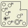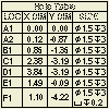

Hole tables display the location and size of holes in a drawing view.
A hole table contains information for selected holes, holes corresponding to a specific hole feature, or all holes in a drawing view. If you add a hole table to a view, a hole tag is associated to each selected hole and a corresponding row is added in the table. If holes are added or removed from the model, or an existing hole is changed, the hole table is updated when the drawing updates.
In addition to individual holes, a hole table can include extruded cuts (except mid-plane extrusions), iFeatures, holes in patterns, center marks, and sheet metal flat patterns.
Hole Table Origin Indicator
The location of the holes in a hole table is measured relative to an origin indicator that is constrained to a point in the view. You place the origin indicator for a view the first time you place a hole table for the view. You can hide an origin indicator after it is placed, but you cannot delete it.
See the Origin Indicator page for more information.
Hole Table Defaults
A hole table uses formats defined in the active hole table style for the drawing. Set up the formats before placing a hole table. Click
Manage tab
 Styles and Standards panel
 Styles Editor
. Then edit the current Hole Table style.
The default format for the hole description in the table is controlled by the associated dimension style of the hole note.
When a hole table is created, alphanumeric auto-indexing is used to generate hole identifiers for holes included in the table. Optionally, exclude particular characters from the auto-indexing sequence on the General tab of the Standard Style panel.
To display dimension values in alternate units, add the alternate unit columns to the table by using the Column Chooser dialog box.
Edit the Dimension Style to set the primary and alternate units for dimensions displayed in the hole table.
Publish DWF data
When you publish a drawing containing a hole table, it is also published to DWF file. Click ![]()
 Export
 Export to DWF or
 ![]()
 Save As
  Save Copy As. Specify the DWF file type and desired options.