 |
A derived part is a new part that references an existing part to copy bodies and other information such as sketches, work features, and parameters associatively. A derived assembly is a new part that references an existing assembly. You can add features to the derived part or assembly. When new features are added to the base component or when derived features are edited, the derived part updates with the changes. Use the Options tab when you derive an assembly to realize additional benefits of rule based component removal and hole patching. Derive an assembly as a surface composite to create the smallest file on disk and to calculate the part significantly faster than a derived solid. A surface composite uses less memory and provides better performance in consuming assemblies. There are two ways to create a derived part; through a "push" method, or through a "pull" method. This section details the steps to create a derived part using the "pull" method. The following commands “push" a derived part out from the source:
You can also use the Derived Component command to insert existing parts and assemblies into a part file as bodies. |
Derived parts and assemblies have valuable application when you want to control changes to models. You can modify the original model and update all derived components to automatically incorporate changes.
Derived parts and assemblies can reduce memory consumption and file size when they are used in a higher level assembly. For example, a derived part is a single body loaded into memory, as opposed to all of the individual components in an assembly. An effective use of a derived part is to use it as an assembly substitute LOD in the assembly it was created from. You can also use the Derived Component command to produce results that are very similar to a derived part created using the Shrinkwrap command.
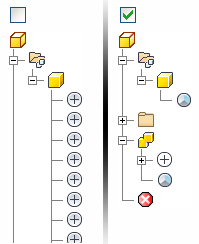
The Options tab contains a check box to create a derived part from an assembly using Reduced Memory Mode. This option creates a part which uses less memory by not caching any source bodies. If enabled, no source bodies appear in the derived part browser. The Options tab also contains settings for part mirror, scale, simplification, part removal, and hole patching.
The left side of the following image shows the browser of part created without reduced memory mode. The right side shows the browser of a part created with reduced memory mode.

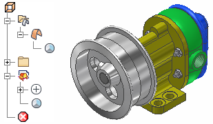
An assembly derived using the Single Composite Feature option creates a part that is a single surface which uses less memory than a solid. A surface body does not cache any source bodies, and cannot participate in interference checks. The surface composite body retains the original part appearance.

How do I know which Derive style to use?
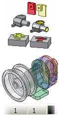
Use the following guide to choose the derive style that best suits your needs.
| |
This option is the default for creating a part file from an assembly. Use this option to create a single body part file from either an assembly or a multi-body part. Edges between parts or solid bodies that share a planar face are merged. |
| |
This option merges the parts in an assembly or the selected bodies in a multi-body part into a single body in a part file. The new part retains the edges between different parts or bodies that share a planar face. The resulting part retains the original appearance of the included parts or bodies that share a planar face. Produces the best results for a drawing view because all edges and seams are retained. |
| |
This option is the default for creating a part file from another part file. Use this option to:
|
| |
Creates a part file that is a single surface body. The resulting surface body retains the seams between planar faces and the original part appearances, such as bitmap threads. Use this option to create the smallest part file on disk. A surface composite part is ideal for use as an assembly substitute LOD or to export in BIM exchange. The resulting surface body cannot participate in the Combine operation or interference checking. The surface body can be used as a Split Tool in the Split command. |
| |
Creates a part file in which individual solid bodies are converted to individual surface bodies. The resulting surface bodies cannot participate in the Combine operation or interference checking. A surface body can be used as a Split Tool in the Split command. |
| When you create a derived part, the derived icon in the browser matches the style option used. Note: If Associative is checked in the Representations tab, then Exclude is not available for any component that is visible in the View Representation you are deriving. Use the View representation in the source assembly to control the inclusion or exclusion of a component.
|
|
Prepare to derive a part
Create a part file, and then click Return to close the sketch if a sketch starts automatically.
On the ribbon, click
Manage tab
 Insert panel
 Derive
, and then select the part or assembly file from which to derive bodies.
To create a single solid body part from the source part, the new part file should not contain any solid bodies prior to the derive operation. To create a multi-body part file, create solid bodies as required and import one or more solid bodies into the part file. You can also choose to include sketch geometry, work features or bodies as surfaces. For inclusion in the new part:
- Only visible, exported 2D or 3D sketches can be selected. The sketch must be unconsumed or shared.
- Only visible, exported work features can be selected.
- Only visible, exported surfaces can be selected.
- Only visible solid bodies can be selected.
Two or more derived part features can be created within a part using the same or different base parts.
When the Show All Objects check box is selected, all derivable objects are listed regardless of their Export status. To hide non-exported objects, turn off the check box.
Derive from a part
If the source is a part file, the default Derive style selection is to maintain each solid as a solid body. If the source part contains multiple solid bodies, you can choose to import the selected bodies as a single body or as multiple bodies. Only visible solid bodies are selectable. If all bodies are visible, no bodies are selected by default.
All features of the selected part are combined into a single feature in the browser of the derived part. By selectively including individual 2D and 3D sketches, work features, and parameters from the base part, you can define individual features from those sketches in the new part.
Derive a work surface instead of a solid from a part
You can use derived work surfaces to define sketch planes, work geometry, and features such as extrude to surface or split. Derived surfaces cannot be used in a Combine operation with a solid body.
Derived surfaces can also be used to define part envelopes to aid designers in calculating space requirements between components.
To create a derived surface from a part instead of the default derived solid bodies; select Body as Work Surface in the Derived Part dialog box.
Derive a surface composite instead of a solid from an assembly
A surface composite derived from an assembly creates the smallest part file on disk and consumes much less memory than the original assembly. You can use a surface composite part as an assembly substitute in a Level of Detail or export it as a representation of the assembly envelope using BIM Exchange. A derived surface composite maintains part appearances such as threads.
Use Derive to insert a component in a part file
You can use the Derive command to insert a part or assembly file on disk as new bodies in a part file. A part can be inserted as a single or multiple solid bodies (if the source part contains multiple solid bodies), or as a work surface. If the source is an assembly, you can select to import the component as:
- A single solid body with merged seams.
- A single solid body with retained seams.
- Multiple solid bodies.
- A surface composite.
Export objects
When you select non-exported objects for derivation in the Derived Part or Derived Assembly dialog boxes, the objects are flagged for Export in the base assembly. Turn on the Show All Objects check box in the dialog boxes to display both exported and non-exported objects in the tree control; an arrow icon ![]() identifies the exported objects.
identifies the exported objects.
You can mark objects for Export while you edit the base component. On the ribbon, click
Manage tab
 Author panel
 Export Objects
.
Export parameters
When you select Exported Parameters in the Derived Part dialog box, any parameter that was marked for export in the original part file is brought into the new file and can be used to create new geometry.
 Author panel
 Export Objects
.
 You specify parameters to export to a derived assembly on the Other tab. Parameters from all components in the base assembly, not just selected components, can be exported.
In the parameters dialog box of the new derived part, exported parameters are grouped in parameters folders. The parameters folder shows the file path and file name of the base body. If there are multiple parameters with the same name, each is incremented to establish a unique name.
Derive from an assembly
Choose the Derive style. If the source is an assembly file, the default selection is to create a single solid body with merged planar faces. You can also choose to import the selected components as multiple bodies or as a single surface composite.
All components of the selected assembly are combined into a single feature in the browser of the derived part. Select bodies to derive on Bodies tab; specify sketches, work geometry, iMates, surfaces (if a part instance), and parameters on the Other tab.
- After selecting an assembly, click OK to include all parts in the assembly in the derived part.
- In the Derived Assembly dialog box, click to toggle the plus symbol
 to a minus symbol
  to subtract the volume of that part from the derived part.
 This capability provides the ability to create two separate parts, position them relative to each other in the assembly, and then perform a Boolean operation that results in a new single part.
Note: You can perform a similar operation in a multi-body part file using the Combine command. - Next to an individual component in the Derived Assembly dialog box, click the plus or minus symbol to change it to a backslash symbol
 . Components marked with a backslash symbol are ignored when the new part is created and are excluded from the derived part. Note: If the Associative check box is selected in the Representations tab, then exclude is disabled for any component that is visible in the View Representation you are deriving.
 - Click
 to specify a component as a bounding box if you do not need its details in the derived component. A bounding box body is created, to which you can add features and make other modifications. Changes to the original component size update the bounding box size.
 - Click the Intersect command icon
 to intersect the selected component with the derived part. To arrive at the Intersect result, Autodesk Inventor makes the following calculations, in this order:
 - Set A: The result of all Includes
 and all Subtractions
  .
. - Set B: The result of all Intersects
 are joined.
 - Final result: The intersection of Set A and Set B. Note: To arrive at a valid final result, at least one body must have a status of Include. For example, if you want to find the derived intersection solid between two subassemblies in a top-level assembly, select Include for the first subassembly and Intersect for the second subassembly.
- Set A: The result of all Includes
- Use the Options tab to specify the simplification level, enable Reduced Memory Mode, or to specify scaling and mirror options.
- If you change any part or assembly from which you have derived a component, you are notified when you next open an assembly that uses the derived component. Click OK to update the derived components.
- Changes made to parts that are open in the active file (and which are also contained in an open assembly) automatically update when you save the change in the part and manually update the derived part.
Common workflow for deriving a part from an assembly
A common workflow for deriving a part from an assembly is:
- Model the individual parts of the assembly.
- Apply assembly constraints to position the parts.
- Optionally create a View or LOD representation with only components to be included visible.
- Save the assembly.
- Open a new part file.
- Select the Derived Component command.
- Select the assembly to derive.
- Select the Derive style.
- If appropriate, use the File Open Options dialog box to specify representations.
Select one or more parts to include in a derived part. From a single assembly, you can select different combinations of parts to create a single derived part with a single body or multiple bodies.
After choosing a part or assembly, you can select bodies in a dialog box to include or exclude in the derived part. You can also include sketches, component work features, exported parameters, iMates, and surfaces.
When deriving from an assembly, you can also specify representations (design, positional, and level of detail). The Associative option for Design View is checked on by default. If Associative is checked in the Representations tab, then exclude is disabled for any component that is visible in the View Representation you are deriving.
Alternate workflow for deriving a part from an assembly
Another workflow for deriving a part from an assembly is to use the Component Derive command in the Assembly Tools. Find these tools in the SDK folder in the installation location. This command streamlines the implementation of the built-in Derived Component command in the part environment. After you select a base component for a part or assembly, this command generates the derived part or assembly using the default options as offered by the built-in command. The only exception is in representations. This command implies the base component's active design view, positional, and level of detail representations to use in the derived assembly.
How are derived parts used?
One of the common uses of a derived part is to explore design alternatives and manufacturing processes. However, there are many other uses for a derived part. Following are some examples of ways you can use a derived part.
- A casting blank can be machined several different ways.
- A standard length of tubing can be machined in different configurations.
- A weldment can be configured several ways, including post-assembly operations such as cuts and holes.
- From an assembly, groups of parts can be subtracted or joined with other parts to create a single part with the desired shape.
- From a multi-body part, derive one or more parts.
- In an assembly, use the derived parts as a layout when designing a framework for an assembly. Edit the original part and update the derived parts to incorporate changes in the layout automatically.
- From a solid, use a derived surface as a layout, or to define part envelopes in assemblies.
- From a solid, use a derived surface as a layout.
- From a part or assembly, derive parameters to use in a new part. You also can use Link Parameters from the Parameters dialog box.
- Derive parameters to use in a new part. You also can use Link Parameters from the Parameters dialog box.
Derived parts are also used to simplify an assembly, protect intellectual property, and to reduce memory consumption. For example:
- From an assembly, specify some components as bounding boxes to reduce memory consumption.
- From an assembly, use the Options tab to simplify the assembly, remove small or hidden parts, or patch holes.
- From an assembly, use the Derive style Single composite feature to significantly reduce the size on disk of the derived part.
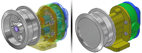
The following image shows the original assembly on the left, and a surface composite part on the right that has optional simplification and hole patching applied. The size of the assembly on disk is 10.6 MB. The size of the derived surface composite part is 670 KB.

Can features be added to parts derived from assemblies?
Creating derived parts is a good way to do operations such as cuts across several parts in a weldment. Because a derived part is a single body, you can customize it with any part feature.
After a part was derived from an assembly, you can add features. This workflow is useful when you want to create a weldment of piece parts and want to add holes or cuts through one or more of the parts included in the derived part.
If you have included one or more components as bounding boxes, a new body is created in the derived part. You can add features, move the bounding box, or change the original component and the bounding box updates.
Can a derived part be a different size from the original part?
When creating a derived part, you can scale it larger or smaller than the original part or create a mirror of the original part using any of the origin work planes. You can update the derived part when changes are made to the original part.
Can a derived part or assembly be a mirrored reflection of the original component?
When deriving a part or assembly, you can specify a full mirror of the resulting derived geometry by selecting the Mirror Part check box in the Derived dialog box.
Do changes to an original part or assembly affect the derived part?
Changes made to the original part or assembly are reflected in the derived part after an Update is performed. If the Associative check box is selected in the Representations tab, then changes made to the source assembly View Representation (such as component visibility) will appear in the derived part after an update. The derived feature shows ![]() in the feature browser to indicate that it needs to be updated. Because an assembly checks component status when the file is opened, parts which were derived from other parts or assemblies are automatically updated when you update the assembly.
in the feature browser to indicate that it needs to be updated. Because an assembly checks component status when the file is opened, parts which were derived from other parts or assemblies are automatically updated when you update the assembly.
Can a derived component be edited?
A derived part or assembly can be edited by double-clicking it in the browser, or by right-clicking it in the browser and choosing Open Base Component. The original file is opened and you can make your changes. To reflect your changes, update the file containing the derived part or assembly.
You can also redefine a derived part or assembly by right-clicking the derive feature in the browser and choosing Edit Derived Part, or Edit Derived Assembly. Use this option to change the parameters you set when the original derived part or assembly was created. Updates are automatically reflected in the current file.
Can a derived part be unlinked from the original part?
You can break the link to the original part or assembly if you no longer want to update the derived part. Right-click the derived part in the browser, and then select Break Link. The derived part becomes a regular feature (or component in an assembly), and its changes are saved only in the current file.
You can suppress the link if you want to disconnect the link temporarily from the source. From the derived feature, right-click and select Suppress Link with Base Component/Assembly. To reestablish the link, use Unsuppress Link with Base Component/Assembly.
You can use Select from base ![]() on the Derived dialog box and go to the source part or assembly to make selections. Then use Accept selection
on the Derived dialog box and go to the source part or assembly to make selections. Then use Accept selection ![]() to transfer the selections from the source to the derived file. In the source assembly, you can use Select filters such as Select All Occurrences or Constrained To to make selections.
to transfer the selections from the source to the derived file. In the source assembly, you can use Select filters such as Select All Occurrences or Constrained To to make selections.
How is appearance information derived?
Appearance information in the source assembly is derived based on the Design View selected in the Representations tab. For master Design Views, appearance is derived from the parts.