Moves one or more faces on a base solid or a feature by a specified distance and direction or by a planar move to specific coordinates.
In the 3D part or assembly environment, moved faces are parametric. In the base solids environment, moved faces are not parametric. In weldments, use Move Face to move a face to leave welding clearance.
| Access: |
In the Part or assembly environment, click
3D Model tab
Right-click the component in the browser and select Edit Solid to activate the Solids environment. Alternatively, you can right-click the base solid in the browser and select Edit Solid from the menu. Then click
Edit Base Solid tab
|
Faces
Selects one or more faces to move.
Automatic Blending
Automatic blending automatically moves adjacent tangential faces and also creates new blends, if necessary. It is active by default in the part modeling, assembly, and solid edit environments.
The Automatic Blending check box is not available in the Edit Base Solid environment.
Free Move
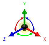
Free Move  allows cumulative linear and rotational transforms of faces using a 3D in-canvas tool called the Triad. You can interactively position a face or feature by dragging the triad in a planar move, axial move, or free movement. The selected area of the triad controls the movement.
When the triad is displayed, select or drag a triad segment to indicate the type of transform you want. You can enter coordinates to move a face or feature precisely using the value input box. When you drag or rotate the triad, the X, Y, and Z coordinates or angular values dynamically update in the value input box.

The colors help you identify the triad axes:
- Red is the X axis
- Green is the Y axis
- Blue is the Z axis
When you first activate the triad, its origin sphere is coincident with the geometry you want to transform. Click a triad section or drag to indicate the type of transform you want. As you select other parts of the triad, you can drag or enter precise coordinates corresponding to your selection.
|
Triad Part |
Description |
|
Arrowheads |
Moves the triad along the axis. |
|
Rotational manipulators |
Rotates the triad around the axis. |
|
Planes |
Moves the triad in the selected plane. |
|
Sphere |
Allows unrestricted movement in the view plane. |
Reorienting the Triad
Triad Reorientation  Whether selecting one or multiple faces, the initial alignment of the Free Move triad depends on the first selected face. In many cases, the triad alignment is satisfactory for the operation you wish to perform. If not, use the Triad Reorientation button in the mini-toolbar to reorient the triad with a different face or feature. Permissible selections include: any face or edge geometry, vertices, work planes, work axes, work points, sketch curves, 2D and 3D points.
Snapping to a face or work point
Snap To  in the mini-toolbar moves a face to align with another face, plane, vertex, or work point. Selected faces can be cylindrical or planar, and planar faces can be at different angles. Only a single face can be moved or rotated at a time.
Direction and Distance
Direction and Distance  moves faces in a specified direction and distance. The direction defaults to the reverse normal for the selected face.
Direction selects the edge or work axis to define direction.
Distance sets the distance faces move. May be expressed as an equation or a recent value selected from list. If desired, select Measure to use the measure command or Show Dimensions.
Points and Plane
Points and Plane  moves faces between selected points on a plane.
Plane selects the plane on which faces move.
Points sets the beginning and ending points to specify move of faces. Draws a temporary line to show the vector.
