| Access: |
On the Insert Joint dialog box, click the Display joints table icon. |
Click the images in the upper section of the dialog box to move from one category of joints to another.
Standard joints
Standard joints are the most commonly used joints. These joints are based on different combinations of rotating and translating degrees of freedom. Available joints in this category are:
![]() Revolution
Revolution
![]() Prismatic
Prismatic
![]() Cylindrical
Cylindrical
![]() Spherical
Spherical
![]() Planar
Planar
![]() Point-line
Point-line
![]() Line-Plane
Line-Plane
![]() Point-Plane
Point-Plane
![]() Spatial
Spatial
![]() Welding
Welding
Rolling joints
Although the images indicate that the joints can be used to simulate gear mechanisms, the actual meshing of the gear teeth is not accounted for. The method establishes a ratio based on geometry selected for the effective rolling radius of the gears.
![]() Rolling: Cylinder on Plane
Rolling: Cylinder on Plane
![]() Rolling: Cylinder on Cylinder
Rolling: Cylinder on Cylinder
![]() Rolling: Cylinder in Cylinder
Rolling: Cylinder in Cylinder
![]() Rolling: Cylinder Curve
Rolling: Cylinder Curve
![]() Belt
Belt
![]() Rolling: Cone on Plane
Rolling: Cone on Plane
![]() Rolling: Cone on Cone
Rolling: Cone on Cone
![]() Rolling: Cone in Cone
Rolling: Cone in Cone
![]() Screw
Screw
![]() Worm Gear
Worm Gear
Sliding joints
![]() Sliding: Cylinder on Plane
Sliding: Cylinder on Plane
![]() Sliding: Cylinder on Cylinder
Sliding: Cylinder on Cylinder
![]() Sliding: Cylinder in Cylinder
Sliding: Cylinder in Cylinder
![]() Sliding: Cylinder Curve
Sliding: Cylinder Curve
![]() Sliding: Point Curve
Sliding: Point Curve
Contact joint
The 2D contact joint is accurate. It detects when a collision occurs, but also allows separation to occur. Because the surfaces have no facets and are not penetrated, there is less chance of anomalies in the results. When working with mechanisms such as cams and followers, use these joints instead of 3D contact joints to accurately investigate the behavior of the mechanism. In some cases, you must create additional geometry on a part or use multiple 2D joints to achieve the appropriate results.
![]() 2D Contact
2D Contact
Geometry modification to ensure a continuous “smoothed” loop.
In order to provide a smoothed continuous loop for the 2D contact algorithm (to improve computation), a slight geometry modification is performed. All discontinuity in the profile is smoothed to have a continuous loop which enables the software to quickly solve the contact. The following example illustrates what takes place within the software.
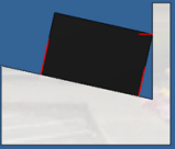 |
The example is a block, with planar faces, in contact with another component where not all faces are not parallel with the block faces. From a distance, the contact vectors (red) look as you would expect them to. |
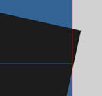 |
If we zoom into the contact area for the non-parallel faces we see there is a slight overlap in the contact. |
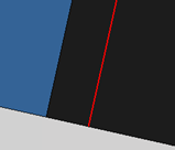 |
Zooming into the contact area for the parallel face we see what is shown on the left. |
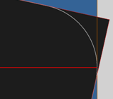 |
This condition occurs because Dynamic Simulation automatically creates fillets o smooth corners, as shown in the image on the left. As you can see, the contact is exact with respect to the fillet. |
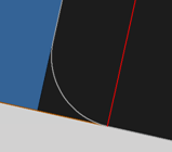 |
In the case of the parallel faces joint, the contact is also exact with respect to the fillet. |
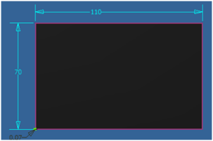 |
The software creates the fillet using the following method:
If the minimal value of 5e-6 mm is reached, then the vertex is not smoothed. In the example on the left, Lmin = 70 mm and the angle is perpendicular (90 deg), therefore the radius equals 0.07 mm. |
Force joints
![]() 3D Contact
3D Contact
![]() Spring/Damper/Jack
Spring/Damper/Jack
| Type | Parameters | Display | Comments |
|---|---|---|---|
| Spiral spring | Stiffness, Free length, Damping | Spiral spring | Default type. The force depends on the distance between the 2 points (stiffness and free length) and the velocity between them (damping). |
| Spring | Stiffness, Free length, Damping | separated, stacked cylinders | Same action as the Spiral spring. The display somewhat resembles a Belleville washer and optimizes display time. |
| Spring Damper | Stiffness, Free length, Damping | Spiral spring and damper | Same action as Spiral spring. The display is like an automobile shock absorber. |
| Damper | Damping | Damper | Only a damping action. The force depends on the velocity between the 2 points. |
| Jack | Input Grapher or Constant | Damper | Applies force parameter directly to the model. The graphic illustrates a jack type mechanism. |