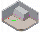
Create an extruded feature or body by adding depth to an open or closed profile, or a region.

Extruded features are building blocks for creating and modifying solid bodies within a part. When created in assemblies, they represent a specific manufacturing process, such as material removal. You specify the direction, depth, taper angle, and termination method for the extrusion. Extruded features can create new bodies in a multi-body part file. A new solid body creates an independent body which you can edit as a separate entity. A solid body can share features with other solid bodies.
You cannot use open profiles to create extrusions as assembly features.
You can add features that refine the shape of one or more bodies. Sketch or select geometry for a new profile, select the participating bodies, and then repeat the extrusion operation, or select a different feature command.
The first feature in a part file is the base feature . If added to other solid bodies, the extrusion can modify the specified bodies with a join, cut, or intersect operation. An intersection creates a solid from the shared volume of the two features and removes any material outside their shared boundaries.
You can use extruded assembly features to cut through other parts.
Types of profiles to extrude
You sketch a profile that represents a cross section, and then extrude it to create a solid, a solid body, or a surface . If you prefer, select an open profile (part features only) or a profile defined by reference geometry, such as boundaries of previously created features. In a multibody part, If you select multiple participating bodies, you cannot use an open profile.
You can create a surface from an extruded profile. Then you can use the surface as a termination plane for other features, or as a split tool for a trim solid or split solid operation.
Primitive shapes
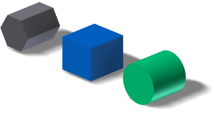
You can automate the sketch creation and extrude process. In the Primitive panel, you can use Box to create a square or rectangular feature or body, or Cylinder to create a cylindrical feature or body.
You cannot create surfaces with the primitive shape commands.
Profile and region for extrusion
The extruded result that you specify, such as a solid, or a surface, determines the geometry that you can select. For example, when you specify a surface extrusion, you can select open or closed loops made up of sketch curves, or projected face edges. When you specify a solid extrusion, with no preselected geometry, you can select either curves or regions. If you preselect a region, you cannot select individual curves or loops to extrude, and if you preselect a curve or loop, you cannot select a region.
To select different geometry, on the dialog box, click Profile, and then reselect. If necessary, zoom in to make selection easier.
Shape propagation types

Shape propagation applies only to open profiles. It describes solutions that are defined through the extension of the open ends of the profile, and by the shape of the body. Shape propagation generates a feature that is robust to topology changes in the part body caused by editing features higher up in the feature tree. The extruded feature is not dependent on a profile defined by specific referenced edges and sketch lines. There are two types of shape propagation: Match Contour and Match Shape.
Termination types with ambiguous solutions
It is good practice to use Distance, Distance-Distance, and To Next termination extents. If the model changes, and your specific termination face no longer exists, recreate the extrusion. If you specify a specific distance, or the next possible face, the extrusion remains intact.
In models where an extrusion could terminate on more than one body (part or surface), to specify the body to use, click Terminator. In an assembly, you select the component face on which to terminate the extrusion. If necessary, zoom in to make your selection.
Some models have ambiguous choices for terminations, such as a cylinder, torus, or irregular surface. When using To and Between extents, to specify the direction of the extrusion, use options on the More tab. By default, the extrusion terminates on the farthest-distance face. Optionally, to terminate the extrusion on the nearest-distance face, click Minimum Solution.
Extrusions in assemblies
In an assembly, an extrusion can be a part feature that was created in a part file in the assembly context. It can also be an assembly feature that was created in the assembly file. For example:
- To add a feature to a part in an assembly, extrude from and to a plane or face of another part.
- To cut through one or more assembly components, create a profile in an assembly sketch, and then extrude as an assembly feature. Its origin and termination planes can be on a part face or a work plane. Selected faces and planes must reside at the same level in the assembly as the extrusion that you are creating.