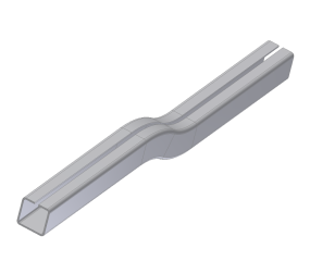
Creating digital prototypes of roll formed sheet metal parts in Autodesk Inventor requires using a Contour Roll feature. The Contour Roll command creates a feature like a Contour Flange that uses a sketched profile as well as a sketched axis of revolution. The profile and axis geometry must exist within the same sketch.
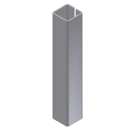
In this exercise, you open a file that contains a straight Contour Flange feature. You add two Contour Roll features and a final Contour Flange. You then create a flat pattern of the resulting folded model.
- Set your project to tutorial_files.
- Open Sheet Metal Parts 2
 contour_roll-start.ipt.
- On the ribbon, click
Sheet Metal tab
 Sketch panel
 Create 2D Sketch
, or right-click and select New Sketch from the marking menu.
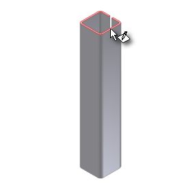
 - When prompted to select a plane or sketch, select the top face of the Contour Flange feature as shown:

Note: All sketch illustrations in this tutorial show the grid displayed. If you recently completed either the Parts 1 or Parts 2 tutorials, you have undisplayed the sketch grid by changing the Application Options. This tutorial does not require the use of the sketch grid and may be completed with the grid displayed or undisplayed.
Next, you project edges into the sketch.