 |
A contour flange is defined using a profile sketch and a straight edge on an existing face. The profile sketch consists of lines, arcs, splines, and elliptical arcs. Contiguous geometry in the profile results in bends in the contour which honor the bend radius value of the sheet metal style. The contour flange can be offset to either side of the profile sketch. Optionally, it can be created using the sketched profile as the flange mid-plane. When a contour flange can be used as the base feature of the design a distance parameter is supplied rather than an edge selection. |
As with flange features, contour flange features can be created using:
-
a specific distance
-
from/to positions defined by existing features
-
offsets from either or both ends of a selected edge
Optionally, create contour flanges by selecting several individual edges or an entire loop of edges around a planar face. Contour flanges created using multiple edges use the corner options specified by the sheet metal style and can be mitered automatically.
While selecting edges for a multi-edge contour flange, edit glyphs are displayed in the graphics window along bends and where the created flanges share corners. These glyphs allow the bend width and corner parameters to be changed from the defaults of the feature using the Bend Edit or the Corner Editfunctionality. All bend widths and corner parameters can also be reset to the default feature style using the Reset All Bends or the Reset All Cornersfunctionality.
Multi-edge contour flanges created with the Apply Auto-mitering check box selected (on the Corner tab of the Contour Flange dialog box) has material trimmed from both flanges which may have interfered along the end of each flange.
Corner considerations
Inventor supports the creation of corners during the creation of flange and contour flange features. These corners display the default corner relief shape when the model is displayed as flat. In certain cases, the created flanges can automatically miter when they would otherwise interfere. You can override the corner relief shape during the creation or edit of the feature and display a glyph in the graphics window when this option is available. Not all corners provide the glyph edit option.
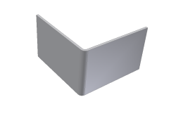
Consider the following model condition:

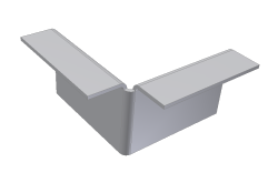
A flange is added to the top edges as follows:

In this case, the outside radius of the added flange is on the opposite side of the outside radius of the bend between the two selected edges. This condition does not offer an edit glyph during creation or edit.
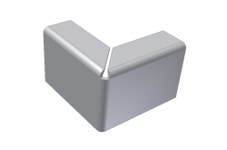
If however you start with the same initial model condition and create the flange in the opposite direction your model appears as the following image:

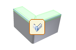
In this case three bends converge upon the corner and their outside radii are on the same side as the outside radius of the bend between the selected edges. This condition provides an edit glyph during creation or subsequent edit as follows:
