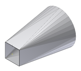
Like its physical counterpart, a folded sheet metal model that forms a continuous tube-like shape cannot be flattened. The Rip feature provides an easy way to create a cut in a face of the model that will allow the flat pattern to be produced.
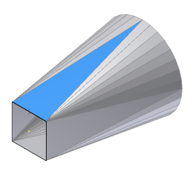
To create a Rip feature, you select a face of the model and (optionally) either one or two points that lie on the selected face. If you select an outside face, any points selected must be on an edge of the outside face. Optionally, you might select an entire face to be removed.
Tip: In this exercise, the point used to locate the Rip feature was added to one of the Lofted Flange profile sketches. Another technique is to create a 2D sketch on a flat face of a Lofted Flange targeted for Press Brake output. Then place a point at a strategic vertex or edge midpoint.
- In the Model browser, click the + to the left of Lofted Flange1. Right-click Sketch2, and select Visibility in the context menu to make Sketch2 visible.
- Adjust your view of the model so that the edge of the sketched square which contains the point is visible on top.

- On the ribbon, click
Sheet Metal tab
 Modify panel
 Rip
.
Rip
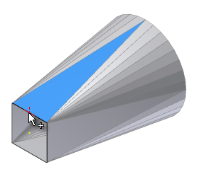
. - Select the face to be ripped (which contains the sketch point along the edge).

- Select the point you previously created that defines the location of the single-point Rip.

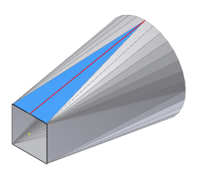
With the point selected, the Rip feature previews.
 Note: The Rip can cut a bend face adjacent to the selected face; however, a rip cannot cut across a bend face and through a second face. In this example, if the point was located anywhere other than the midpoint of the edge, the rip could not be created.
 - Click OK in the Rip dialog box to create the Rip feature and close the dialog box.
- In the Model browser, right-mouse select Sketch2, and click Visibility in the pop-up context menu to switch off Sketch2 visibility.