Create a sprue

Add a sprue as the first step in defining the feed system for the model you have been working on in the previous tasks.

Before inserting a sprue, you will need to specify the sprue properties.

  1. Click Geometry, Home tab (Home tab > Create panel > Geometry) to open the Geometry tab.
  2. Click Defaults, Geometry tab (Geometry tab > Properties panel > Defaults) and select Sprue Properties, Geometry tab Sprue Properties from the Defaults drop-down list.. The Sprue properties pane appears.
  3. Select Cold in the Sprue type drop-down list and Circular Tapered in the Sprue shape drop-down list.
  4. Enter a Start diameter (1) of 3 mm and an End diameter (2) of 5 mm then click OK.

    The simplest way to build a feed system is to use a grid to define the element start and end point.

  5. Click Defaults, Geometry tab (Geometry tab > Properties panel > Defaults) and select Grid Size, Geometry tab Grid Size from the Defaults drop-down list. The Define grid pane appears.
  6. Set the Grid size to 10 mm.
  7. In the Origin section, select Center of part from the Position drop-down list.
  8. Click OK.
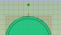
  9. Click Sprue, Geometry tab (Geometry tab > Feed System panel > Sprue). The Create sprue pane appears and the mold is shown from above with a grid superimposed over it.
  10. Ensure the Display Grid and Snap to grid checkboxes are selected in the Grid settings box.
  11. Click on a grid point that is in line with the injection location, then click OK in the Create sprue pane.

  12. Rotate the model to investigate the sprue you have just created.

The sprue has been defined. In the next task you will create the runner.