Adjust the orientation of the models in the family mold.
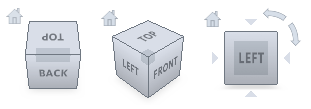
Tip: Using the  ViewCube click Front View to display the model in the same orientation as in the steps below.
 ViewCube click Front View to display the model in the same orientation as in the steps below.
 - Click
 (Home tab > Create panel > Geometry) to open the Geometry tab.
 - Click
 (Geometry tab > Layout panel > Translate). The Translate dialog appears.
 - Select the mouse_base part. The model turns pink, which indicates this model is selected to be translated.
- Enter -200 in the X: text-box, and then click Apply. The
mouse_base
model is moved 200 mm in the negative X direction. Tip: Click
 (View tab > Navigate panel > Zoom All) to rescale the Model pane.
- Now the models need to be oriented in relation to each other. Click
 (Geometry tab > Layout panel > Rotate). The Rotate dialog appears.
 - Click on the mouse_base part. The model turns pink. This specifies which model is to be rotated.
- Select the Use part center option, to rotate the part about its center.
- Enter 180 in the X: text-box, then click Apply. The models should now be positioned as follows:

Tip: You can also click or
or  to rotate the selected model by steps of +90° or -90° about the X, Y or Z axes.
 - Click Close to exit the Rotation pane.
- You will now place an injection location on the mouse_base model. Rotate the model to investigate the model geometry.
- Select the Tasks tab from the top of the Project panel.
- Click
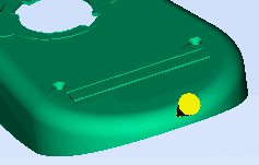
 (Home tab > Molding Process Setup panel > Injection locations) and click on the model to set the location as shown.

- Right-click in the Model pane and select Finish Set Injection Locations from the context menu.
- Right-click on the injection location and select Properties from the context menu. The Edit properties dialog appears.
- Enter the following coordinates in the relevant text box:
X -130
Y: 40
Z: 16
Note: The X value specified is not on the model surface. This value was adjusted to about -131 so that the injection location is actually on the model. - Click Apply, and then Close to exit the Edit properties dialog.
- You will now align the injection locations. Using the
 ViewCube click Bottom View to display the models in the same orientation as below.
 - Make sure all injection cones are deselected.

- Click
 (Geometry tab > Layout panel > Align). The Align dialog appears.
 - Click on the mouse_top injection cone, then hold down the Ctrl key and click on the mouse_base injection cone.
- Select Z direction from the Alignment direction drop-down list, then select Cavity 1/ Gate 1 from the Align with part drop-down list. This aligns the second cavity ( mouse_base ) with the first cavity ( mouse_top ).
- Click Apply Both injection points are now aligned on the X axis.

- Click Close to exit the Align dialog.
In the next task, you will create a runner system for the mold.