Use this option to define code parameters of the member type. There are two ways to access this option:
- Click the New member type option in the Member Type dialog
- Click the Parameters button in the Definition dialog.
Dialog elements
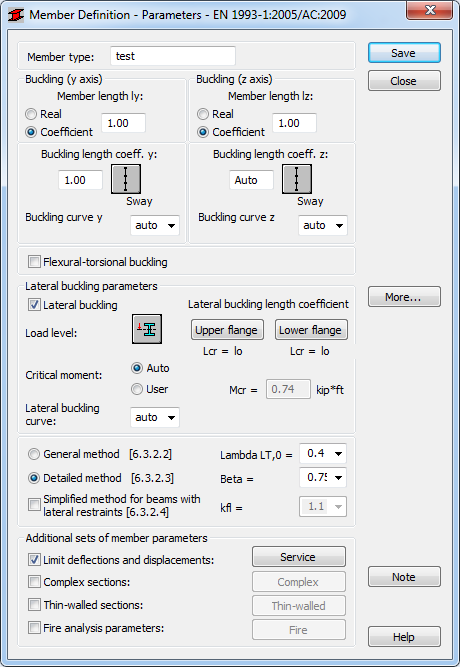
- Member type
- Specify a name for the member type.
- Buckling (Y axis) or (Z axis)
- Determine the length of a member for the appropriate plane. There are two ways to define this length:
- Select Real and specify the actual member length.
Enter 1.0 to specify that the actual length will be adopted for each member defined using the category as Ly.
- Select Coefficient and specify a coefficient by which the real member length should be multiplied to obtain the required value. For instance, if the value 0.25 is entered, it means that the relevant length equals 1/4 of the real length. Use this method to define several members of different actual lengths simultaneously (with additional supports equally spaced) or if the parameters are to be saved as a category.
- Select Real and specify the actual member length.
- Buckling Length Coefficient
- Define the member buckling length coefficients in both directions.
The actual member length (or the sum of the component member lengths) is entered automatically.
The buckling length coefficient depends on the end-support conditions of the member nodes in the buckling plane. The member buckling length are defined in the Buckling Diagrams dialog, and is opened by clicking the icon representing a selected type of the member buckling model. It includes typical diagrams of the member support; when one is selected, the coefficient value will be accepted or calculated automatically.
The icons in the dialog are divided into two groups:- Typical (code) methods of member support and corresponding values of buckling coefficients,
- Icons of options used for calculating the buckling coefficient for columns of multi-story frames.
Buckling is considered in calculations when a compression force appears in the member, even if it is negligible in comparison to other internal forces. A separate analysis to determine if buckling effects may be disregarded, is not performed. To eliminate buckling effects from the calculations, the last icon has to be selected, and buckling will be disregarded in the calculation process.
- Lateral Buckling Parameters
- Provides options used during verification of lateral buckling for the member: lateral buckling type, load level, critical moment, and lateral buckling length coefficient.
- Lateral buckling
- Select this option to take into account lateral buckling during the calculations.
Click the relevant icon to open the dialog for the definition of appropriate parameters.
- Load level
- Determines the lateral buckling conditions.
Specify the level at which the load is applied by defining the ordinate of the load level height in the system of member section axes. Assuming that lateral buckling occurs when a load is applied to the member in the XZ plane, only one coordinate is provided. It is a relative value from the interval <-1.0,1.0>. If a load is applied at a characteristic point of a section - upper or lower flange, etc., it is enough to choose the relevant icon and the coordinate value will be adopted automatically.
- Critical moment
- Select if you want to calculate the elastic critical moment for lateral-torsional buckling automatically or manually.
If you select the User option, you need to enter a value for the specific critical moment Mcr.
- lateral buckling curve
- Select a type of curve from the list.
By default, Robot selects automatically one the curves: a, b, c or d, based on the section type and dimensions and the lateral buckling method (according to Tables 6.4 and 6.5 of the code). If you do not want it to be selected automatically, decide which curve to use in calculations by selecting a, b, c, or d.
Lateral buckling calculations requires the distance between member sections protected against torsion (lateral buckling length). It is necessary to distinguish two lateral buckling lengths as the upper or lower flange which can be fixed separately. For a compressive stress, it is possible to occur in the upper or lower flange for different load cases. Therefore, a value of the coefficient is given by which the base member length should be multiplied to obtain the lateral buckling length. The length Iz is taken as the base length. Enter the coefficient value directly or select the icon representing a typical fixing case for which the coefficient will be automatically chosen.
According to the code Belgian NAD NBN EN 1993-1-1/AC : 2009, calculations of cantilevers with and without warping effects differ. Therefore, the Cantilevers without warping effects option is available after you select this code. This option is active only if the
 Lcr = 2 lo or
  Intermediate bracings option is selected for the upper or lower flange in the Lateral Buckling Length Coefficient dialog. If you select other options from this dialog, the Cantilevers without warping effects option is not active.
 - Lateral buckling calculations method
- Select the method to use for the calculation of lateral buckling.
- General method (see section 6.3.2.2 of Eurocode 2005)
- Detailed method (see section 6.3.2.3 of Eurocode 2005)
- Simplified method for beams with lateral restraints (see section 6.3.2.4 of Eurocode 2005).
Note: The Auto option is available for the Lambda, Beta and kfl parameters in the selection list for some National Application Documents. When you select this option, the program will automatically match the values of the coefficients in accordance with given NAD's recommendations. The selection list contains predefined values of the parameters; the user can enter any value of the parameter.Note: The symbols are explained in the Results dialog (the Detailed Results tab).The dialog contains definitions of all parameters assumed in steel member calculations and result values obtained after member calculations.Click More to open an additional dialog for definitions of the remaining member type parameters provided in the code as: load type, section parameters, etc.
- Additional sets of member parameters
- Select an additional set of member parameters if necessary.
- Limit deflections and displacements: select this option, and then click Service to open the additional Serviceability dialog. Member type parameters (limit displacements, camber) can then be defined
- Complex sections: select this option, and then click Complex to open the additional Complex section (Eurocode3) dialog or Complex section (CM66) dialog. The parameters of complex members can then be defined
- Thin-walled sections: select this option, and then click Thin walled button to open the Thin-walled section dialog opens. The dialog includes the definitions of parameters of the thin-walled member type used during design and verification of steel members of thin-walled sections, according to the guidelines of the EC3 EN 1993-1-3 code
- Fire analysis parameters: select this option, and then click Fire to open the additional Fire dialog where parameters of the fire resistance of a member are defined.
Click Save to add the member type of the defined name and parameters to the list of previously defined steel member types.