In the course of running the analysis, you may be presented with an error or warning message from the decoders (Analysis Analysis Check Model) or the processors (Analysis Analysis Run Simulation). The following is a list of the messages.
- Although these error messages are mostly listed in alphabetical order on this page, similar messages with the same symptoms and corrections are listed together even though the error message is not listed alphabetically.
- Therefore, search this page (use Ctrl+F) for the key text from the error message. No need to include any numbers in your search since node, element, stiffness values, and even error numbers may be different in your model.
Fatal Errors:
Fatal errors prevent the decoder from producing usable files for the Results environment and the processors, or stop the analysis before producing all the results. (Since the deflections are calculated first, then the stresses are calculated, it is possible to get deflections results even if the analysis does not complete, depending on when the error occurs.)
Error Messages
error: connectivity wrong for element
node I =XX
node J =XX
node K =XX
node L =XX
or
error: element is probably inside-out
check node order for element number XX
or
error: geometry wrong for element
node I =XX
node k =XX
node J =XX
nodes I, J, and K are collinear
or
error: geometry wrong for element
elements must be numbered in anti-clockwise order
node A = XX
node B = XX
node C = XX
node D = XX
node E = XX
node F = XX
node G = XX
node H = XX
nodes A, B, and C are collinear
These indicate that the element created by connecting node numbers I, J, K, and L (or A, B, C,) is poorly shaped. Some element types require the nodes to be ordered in a clockwise or counter-clockwise direction, or the order defines the outward direction from the element. Or three nodes could be co-linear (in a straight line). For some reason, the element was created without following these rules.
If the model will load into the Results environment, select either the nodes or element indicated using the Results Inquire Inquire Current Results Specify or Results Inquire Inquire Element Information Specify. From the location in the model, review the lines forming the element in the FEA Editor. Correct the lines forming the element if possible.
If the model does not load into the Results environment, or remeshing the bad element does not eliminate the problem, it may be necessary to translate the FEA database to a text format and edit the element definition manually. Reordering the nodes in the proper sequence should fix the problem. See the page General Options: Using the Database Translation Utility for instructions.
error: element temp outside material table
When using temperature-dependent material properties, the properties are entered into a table. This table is interpolated at the applied temperature to calculate the material property. The temperature in the model is outside the range of the temperature input; thus, the properties cannot be interpolated. Edit the material properties and extend the range of material data.
error: inadmissible negative eigenvalue calculated in eigsol
A negative eigenvalue is found - most likely an ill conditioned model. Therefore, the natural frequency cannot be calculated. Check the model for distorted elements (Results Contours Other Results Element Properties in the Results environment). If possible, use boundary conditions or boundary elements to stabilize the model.
error: k-node on local 1 axis - element no. N
The beam element local axis orientation node (the k-node) is located inline with the beam element. Therefore, a unique orientation cannot be created. Locate element number N in the Results environment (Results Inquire Inquire Element Information Specify), then locate the same line segment in the FEA Editor. Change the orientation of the line so that the k-node is not co-linear with the element. See the paragraph Beam Element Orientation on the page Setting Up and Performing the Analysis: Linear: Element Types and Parameters: Beam Elements for details on aligning the beam elements.
error: main array space exceeded problem size must be reduced
required array size = XX
available array size = YY
Not enough memory to hold model data for analysis. The analysis needs ( (XX - YY) x 8 ) more bytes of RAM to run the model. Possible solutions to this problem include the following:
- Allocate more memory to the analysis on the Setup Model Setup Parameters Solution tab.
- Run the analysis on a computer that has more RAM.
- Reduce the size of the model.
error: non-positive Jacobian determinant degenerate geometry or backward numbering for element number XX
A distorted element was found that has negative volume (non-positive Jacobian). One cause is the order of the node numbers is not correct, but it could also be a poorly-shaped element.
If the model will load into the Results environment, select either the nodes or element indicated using the Results Inquire Inquire Current Results Specify or Results Inquire Inquire Element Information Specify. From the location in the model, review the lines forming the element in the FEA Editor. Correct the lines forming the element if possible.
If the model does not load into the Results environment, or remeshing the bad element does not eliminate the problem, it may be necessary to translate the FEA database to a text format and edit the element definition manually. See the page General Options: Using the Database Translation Utility for instructions.
Error: Number of integration points must be greater than 0.
The number of integration points for the brick elements is missing. Edit the Element Definition for each brick part and click OK to set the defaults.
error: temperatures must be input in ascending order
or
error: temperatures not in ascending order
Temperature-dependent material data must be in ascending order. Edit the material properties for the part and use the Sort button to sort the data.
error: wrong element data - element no.
An error was found in the input data. Check that the cross-sectional properties are entered (thickness for plate and 2D planar elements; area and inertias for each beam cross-section; and so on) Check that the material properties are complete.
error: exactly zero pivot encountered during numeric factorization; matrix is singular.
or
error: your model has a stiffness change which is too big or not enough mass Equation
number = XX
or
error: your model isn't tied down enough make sure each DOF is set somewhere
See the Tip Stiffness Problems at the end of this page for general solutions.
error: zero time step specified
At least one time step is required. Enter the time step information on the Analysis Parameters dialog (Setup Model Setup Parameters Parameters).
Geometry not correct for element Part #n, all rigid elements in a part must share a master node.
Rigid elements within one part must be connected together at one node. The elements in the indicated part do not satisfy this criteria. Redraw the rigid elements to eliminate this error, or place them on separate parts. See the page Setting Up and Performing the Analysis: Linear: Element Types and Parameters: Rigid Elements for more information.
Matrix might be not positive definite.
This error occurs with the iterative solver when a solution to the matrix could not be found. This often occurs when the model is not statically stable. Review the model to be certain that each part is connected to other parts which in turn are restrained. Remember that the entire model needs to be statically stable in all six directions: three translations and three rotations.
If the model contains gap elements or contact, review the tips on the page Performing Analyses with Gap Elements.
Also review the material properties and other stiffness parameters (thicknesses of plate elements, cross sectional areas of beams, and so on) to be certain that the properties related to the elastic stiffness of the model are correct.
Finally, using a different solver (such as the sparse solver) may let the analysis run to completion, or it may report a different error message (model may not be tied down enough) which identifies the problem area. Due to the nature of the iterative solver, it cannot identify where the problems occur in a model whereas the sparse solver can identify problem areas.
PROCESS ERROR REPORTED BY SUBROUTINE xdslfa
Any type of error from the subroutine xdslfa indicates that the matrix cannot be solved by the selected solver. Check whether the model is statically stable. Check for missing boundary conditions or parts that are not fully restrained in all six directions (three translations, three rotations), or parts that are not connected to other parts. Also see the page Model Not Tied Down Enough. Another option is to try a different solver, which may be less sensitive to stability problems, or may report the error in a different format which provides other clues.
Warning Messages
No Log File Exists
This message can occur during the Check Model command or during the verifying model phase of an analysis. If there is a geometry error or warning, you can view the warning. Selecting Yes may lead to the No log file exists message if any folder in which the model is stored or the model name itself has characters that the software does not recognize. Try renaming the model and storing it to a short, simple path located on your local computer. (Running models on a network drive is not recommended.)
Shear modulus G is inconsistent with X calculated from the elastic modulus and Poisson’s ratio for isotropic material part N. Note: Material is not truly isotropic
For an isotropic material, the shear modulus of rigidity G is related to the modulus of elasticity E and Poisson’s ratio ν as follows: G= E/2/(1+ ν). The material property that you entered (G) does not satisfy this equation (value X) for the indicated part number. You should correct the material properties.
Warning Angular acceleration multiplier set but angular acceleration not set.
This indicates that some load case has a value entered for the Angular Accel column of the Load Case Multipliers table (Setup Model Setup Parameters Multipliers tab), but the value of the centrifugal angular acceleration is zero. Thus, there will be no loads due to angular acceleration. Optionally, enter the data if angular acceleration.
Warning Centrifugal force multiplier set but no rotation rate set.
This indicates that some load case has a value entered for the Rotation column of the Load Case Multipliers table (Setup Model Setup Parameters Multipliers tab), but the value of the centrifugal rotation rate is zero. Thus, there will be no centrifugal loads due to rotation of the model. Optionally, nter the data if angular velocity.
Warning: current unit system does not match the unit system used in modal analysis, results might be incorrect.
This can occur with a dynamic analysis that uses the results from a modal analysis. The Model Units must be identical in both models. If not, this warning is given. Since no conversions are performed between the results in the modal analysis to the units in the dynamic analysis, the results of the dynamic analysis may be wrong. You should make the Model Units identical in the two models and rerun the analyses.
Warning: Found MPCs defined that currently require AMG solver, switch to AMG iterative solver.
The model contains either multi-point constraints (MPC) or cyclic symmetry (which uses MPCs), and the iterative solver is required for the MPC solution. Although the type of solver was set to something other than Automatic or Iterative (AMG), the iterative solver was used during the solution.
warning: max/min stiffness ratio = x
The stiffness matrix has a range of stiffnesses (maximum divided by the minimum) that is very large. The solution of the matrix may not be accurate due to round-off errors. See the Tip Stiffness Problems at the end of this page for general solutions.
Warning: no mode/frequency is found in the specified range.
Warning: the model may be poorly posed.
In a linear critical buckling analysis, the processor may fail to find a solution if the stiffness ratio is large. This can occur when smart bonding exists in the analysis and a large penalty multiplier is used. Try reducing the penalty multiplier.
warning: your model may not be tied down enough or you may have a change in stiffness somewhere in your model which is too abrupt. Check DOF:
The model is either unrestrained in one of six directions (insufficient boundary conditions to make a statically stable model), or an abrupt change in stiffness was detected (which due to round-off is not easily distinguished from an unstable model.) See the Tip Stiffness Problems at the end of this page for general solutions.
Warning: zero stiffness replaced by 1.0E+20 at EQN#m, NODE#n dir
The processor has detected a node (number n) in the model that is free to move in the indicated direction dir. Instead of stopping the analysis with an error, the processor added a stiffness to the matrix (essentially a boundary condition) in the indicated direction so that the analysis can proceed. The user should locate the node in the Results environment (click Results Inquire Inquire Current Results Specify button to enter the node number) and confirm that the artificial stiffness has not affected the results.
This warning often occurs when working with 2D truss models. Since the truss element is a 3D element, and because each joint is pinned, the truss elements cannot prevent the unrestrained nodes from moving in the out-of-plane direction. See Figure 1. Other element types can produce similar warnings.
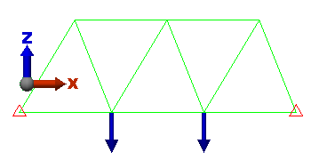
Figure 1: Example 2D Truss Model
Since the structure is planar and the joints are pinned, the truss elements provide no resistance or axial force in the Y direction. Therefore, a warning is given for all nodes except for the two with a Ty boundary condition.
- Stiffness Problems: stiffness and model not tied down problems share a number of common problems and solutions. For example,
- Axisymmetric elements must be on the +Y side of the Z axis. The Y coordinate is the radius of the cross section, and the radius must be positive. Check the location of the model if using 2D axisymmetric elements.
- The material properties or cross sectional properties may have been entered incorrectly (1 psi modulus instead of 1E7 psi). Check that the input is reasonable. If simulating rigid elements by entering large properties, reduce the stiffness to see if the stiffness values change in the warning or error message.
- The stiffness of plate and 2D elements can be affected by the shape of the element. Do a Check Model if necessary to get the model into the Results environment, then use the Results Contours Other Results Element Properties Warp Angle and Node Angle to review the quality of the model. Any elements that are severely warped (over 5 degrees in some cases) or distorted (node angles deviate greatly from 60 degrees for a triangular element or 90 degrees for a quadrilateral element) can produce abnormal stiffness.
- The model is unrestrained in one of six directions (insufficient boundary conditions to make a statically stable model).
- Another option is to try a different solver, which may be less sensitive to stiffness and stability problems, or may report the error in a different format which provides other clues.
- See the following page Model Not Tied Down Enough for additional instructions on locating problem areas.