A good mesh is essential for accurate and dependable results. Autodesk Simulation CFD, formally known as CFdesign, has a long tradition of innovative meshing technologies including Mesh Enhancement, Automatic Mesh Sizing, and Automatic Refinement. In this version, we continue this tradition with the addition of Adaptive Meshing, Interactive Mesh History, and the introduction of High Performance Meshing.
Adaptive Meshing (and mesh sensitivity study)
Since its introduction, Automatic Mesh Sizing has greatly simplified the modeling process. Automatic Mesh Sizing defines a mesh that is optimized for the model and accurately represents every detail of the geometry.
A good representation of the geometry is only one requirement for a high fidelity solution. For example, the flow on a simple model with a uniform mesh can contain significant gradients. The results on the coarse mesh may not be highly accurate, but they do indicate flow trends. These trends can be used to identify where the elements should be concentrated to improve solution accuracy.
Mesh Adaptation uses solution results to progressively improve the mesh definition. The simulation is run several times. Each time the results in the previous cycle are used to improve the mesh in the next cycle. The result is a mesh that is optimized for the particular simulation. The mesh is finer for high gradient regions, and coarser elsewhere.
When Mesh Adaptation is enabled, the following occurs:
- A baseline scenario is run to completion.
- The mesh is changed (often refined) based on velocity, pressure, and temperature (if available). The simulation is run to completion.
- The process repeats for each Adaptation cycle.
The result is an intelligently refined mesh that is tuned for the flow and temperature results fields.
An example of Mesh Adaptation
To illustrate the effect of Adaptive Meshing, we have solved for the flow through this industrial water valve:
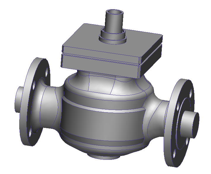
There are several regions in the valve which are not closely bounded by geometry. We can assume there will be flow activity, however, due to the momentum of the water. We will see that the flow recirculates, accelerates, and changes direction abruptly. Because the geometry does not have a great deal of curvature, the mesh may not capture the flow as well as we would like.
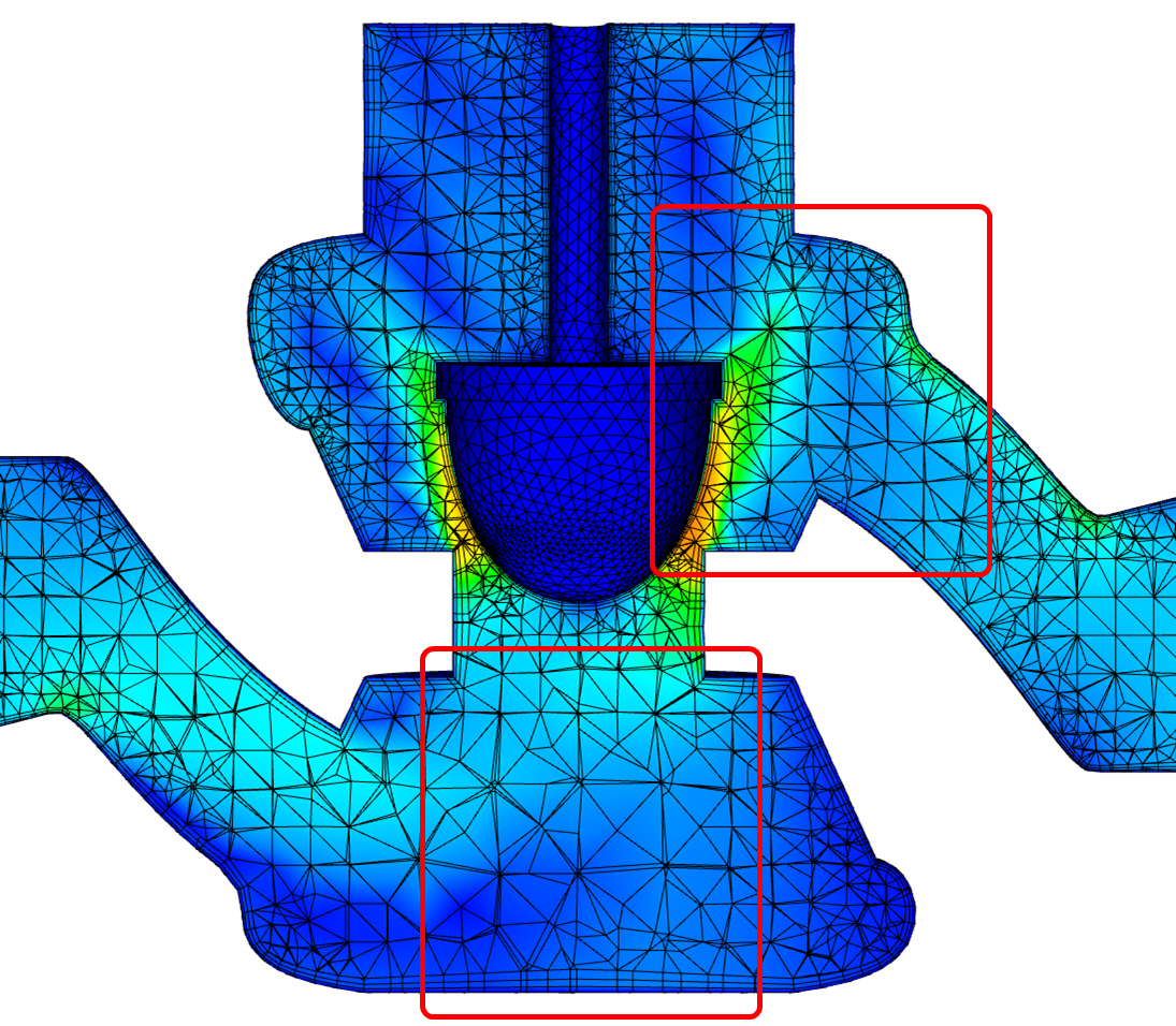
Initial Mesh
In the first meshing cycle, Automatic Mesh Sizing defines a default mesh distribution based only on geometric curvature. Note that the mesh is coarse upstream and downstream of the poppet where there is little geometric influence:
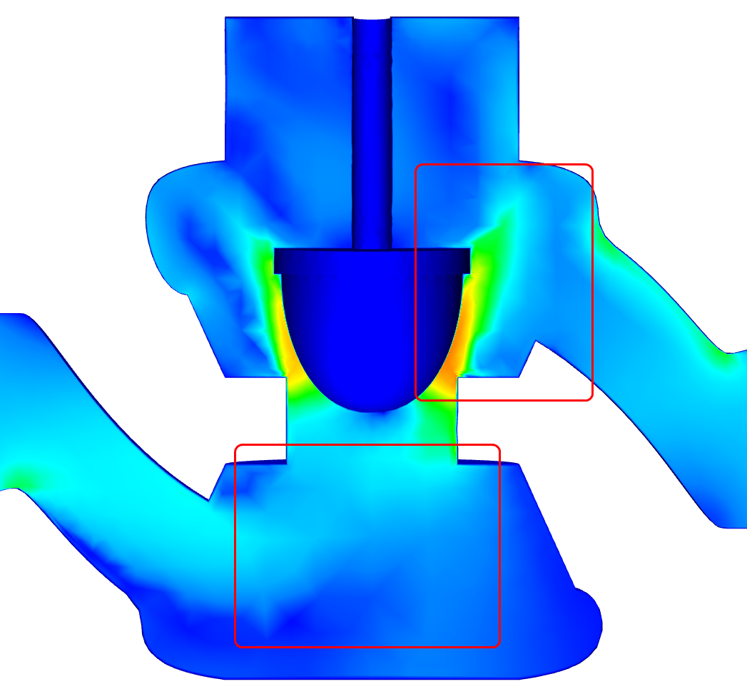
The resultant flow appears jagged because of the sparse mesh distribution. The flow upstream of the poppet is not well defined, and the jet through the annular throat region appears to disperse immediately downstream of the poppet before reattaching to the outlet wall:
Adapted Mesh
After several adaptation cycles, the mesh is refined enough to capture these and other flow features with much greater fidelity:
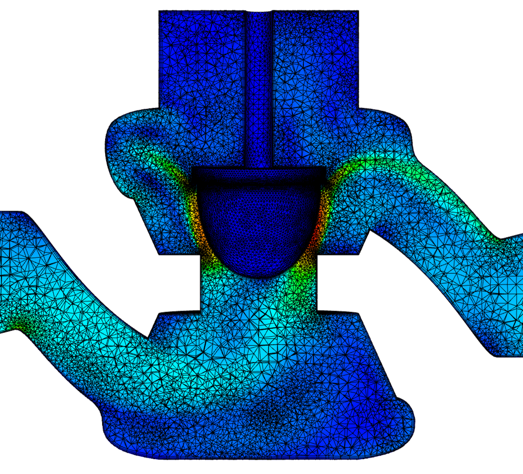
The final results are much clearer, and reflect the physical behavior of the water as it flows through the valve:

Note the clearly defined flow bifurcation and recirculation upstream of the poppet. The jet through the annulus is very sharp, and it retains its cohesion as it attaches to the outlet wall.
Mesh Definition History in the Design Study Bar
Quando si definisce una mesh mediante il Ridimensionamento automatico della mesh, viene definito un processo utilizzato dalla Creazione mesh per generare la mesh. A differenza dei materiali e delle condizioni al contorno, una definizione della mesh è un gruppo di comandi inviati in ordine specifico. Quando si modifica l'ordine di tali comandi, spesso viene modificata anche la mesh risultante.
La sezione Dimensioni mesh della barra Studio di progettazione elenca ogni passaggio della cronologia della definizione della mesh. Ciò comprende anche il caso in cui viene richiamato il comando Ridimensionamento automatico, le regolazioni delle dimensioni e l'applicazione del comando Propaga modifiche. Ciascun passaggio viene elencato come sezione separata e non può essere modificato o eliminato dalla definizione della mesh.
La definizione della mesh si basa su tutti i passaggi della cronologia. Alcuni comandi di definizione della mesh apriranno finestre di dialogo contenenti domande relative al ripristino delle impostazioni di regolazione esistenti o alla rimozione delle dimensioni della mesh esistenti. Le risposte a tali domande influenzano la definizione corrente della mesh, ma non rimuovono i passaggi precedenti nella cronologia. I nuovi passaggi della definizione potrebbero alterare la distribuzione e "annullare" gli effetti dei passaggi precedenti.
Segue un elenco dei principali vantaggi della cronologia mesh:
- Completa visibilità di ogni passaggio che definisce la mesh. È più semplice ricreare la stessa mesh su un altro modello o in un secondo tempo.
- È possibile "ripristinare" una definizione della mesh mediante la disattivazione o l'eliminazione di uno o più passaggi. In questo modo è più semplice osservare l'effetto di una modifica o correggere gli errori.
Mesh Refinement Region Controls
The Mesh Refinement Regions dialog has been improved to make it more interactive. Use this table to define the following parameters of your refinement regions:
- Shape
- Position
- Size
- Orientation
Additionally, use the table to view and modify the specifications of existing regions.
These controls complement the graphically-based tools for defining refinement regions.
High Performance Meshing
To improve meshing performance, the Autodesk Simulation CFD mesher leverages multiple computing cores. This reduces the amount of time required to generate large meshes, and better utilizes high performance computing hardware.
To enable multi-threaded meshing, enable this flag in the Flag Manager
The argument, n, is the number of cores to be used by the mesher.
Notes:
- Autodesk Simulation CFD automatically detects and uses the available cores on the computer, up to the value specified in the flag argument.
- Multi-threaded meshing is not available for models launched from the Pro/Engineer Mechanica option.
- Multi-threaded meshing does not support Volume Growth rate and Boundary Layer blending options from the Advanced Meshing Controls dialog.
- For meshes that contain both tetrahedral and extruded (wedge) elements, Multicore meshing generates the tet elements, and single core meshing generates the extruded elements. The transition is automatic and transparent.