Using this option, you can transfer formwork drawings of selected positions (elements) of a structure model to Autodesk AutoCAD Structural Detailing - Reinforcement.
To export to the Reinforcement module:
- Run positioning of structure elements (see: Automatic positioning)
- On the Positions tab of the Object Inspector dialog, select positions (of the same or different types), right-click, and click Export formwork drawings to Reinforcement.

In the Formwork drawing wizard dialog:
- Indicate drawing positions
These may be of the same element type (such as beams) or of different types (such as beams, columns, and spread footings).
- Indicate the file where a formwork drawing will be generated
- By entering its name for New file
- By selecting a previously saved file for Add to the existing file
- Click Next.
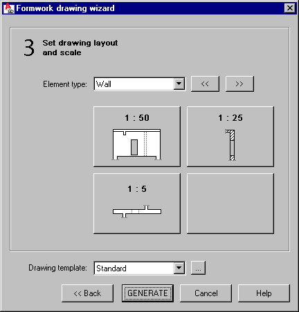
- Specify the drawing layout and scale for all the selected types of structure elements
The Element type list contains only the types selected in the Object Inspector dialog. The drawing layout and scales are determined by the settings in the Drawing template manager dialog.
- Click Generate.
Autodesk AutoCAD Structural Detailing - Reinforcement runs in integrated mode with the Formwork Drawings module. A DWG format file is produced.
When you export formwork drawings to the Reinforcement module, an additional toolbar (Formworks) -displays. Its options allow you to manage objects from Autodesk AutoCAD Structural Detailing - Formwork Drawings.

Use the toolbar and the context menu to:
- Modify graphical parameters - after you select this option, the Modification of display parameters dialog displays, where you can modifying parameters of graphical display of selected objects (see also: Graphic representation of objects).
- Create section - after you select this option, you can define a section through a chosen object:
- Click the icon on the toolbar
- Indicate a view (drawing)
- Determine successive points defining the section
- Define the section depth
- Indicate the section location in a drawing.
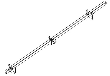
- Create 3D view (available only from the context menu) - after you select this option, you can create a 3-dimensional drawing (representation) of a selected object. The 3D view includes all elements adjoining the chosen element (according to the settings defined in the Adjoining elements dialog). To create the 3D view:
- Select Create 3D view from the RBCRELX context menu
- Indicate the contour of an element for which the 3D view should be generated
- Indicate the location of the 3D view in a drawing; an example 3D view of a beam is shown below.
Elements loaded from Autodesk AutoCAD Structural Detailing - Formwork Drawings to the Reinforcement module display in the Object Inspector dialog:
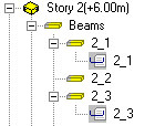
- On the Model tab in Autodesk AutoCAD Structural Detailing - Reinforcement, using the element structure (hierarchy), as shown. Also see the description of the Element manager dialog.
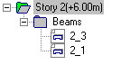
- On the Positions tab in Autodesk AutoCAD Structural Detailing - Formwork Drawings, and notated with
 , as shown, which indicates that the position has a formwork drawing created in the Reinforcement module. Double-clicking this icon runs Autodesk AutoCAD Structural Detailing - Reinforcement and opens the formwork drawing of the given position.