Below is a list of all options available in Autodesk AutoCAD Structural Detailing - Formwork Drawings. The list includes several access methods for each option (menu path, ribbon, icon, toolbar and command line) and short descriptions of the options.
See also: Ribbon
|
Definition |
|
|
Wall |
Opens the Wall: definition dialog, where you can define walls in a structure model. Menu: Formwork Drawings > Define > Wall Ribbon: ASD - Model > Elements > Wall Toolbar: Define > Wall Command line: RBCX_DEF_WALL |
|
Column |
Opens the Wall: definition dialog, where you can define columns in a structure model. Menu: Formwork Drawings > Define > Column Ribbon: ASD - Model > Elements > Column Toolbar: Define > Column Command line: RBCX_DEF_COL |
|
Beam |
Opens the Beam: definition dialog, where you can define beams in a structure model. Menu: Formwork Drawings > Define > Beam Ribbon: ASD - Model > Elements > Beam Toolbar: Define > Beam Command line: RBCX_DEF_BEAM |
|
Slab |
Opens the Slab: definition dialog, where you can define floor slabs in a structure model. Menu: Formwork Drawings > Define > Slab Ribbon: ASD - Model > Elements > Slab Toolbar: Define > Slab Command line: RBCX_DEF_SLAB |
|
Stairs |
Opens the Stairs: definition dialog, where you can define stairs in a structure model. Menu: Formwork Drawings > Define > Stairs Ribbon: ASD - Model > Elements > Stairs Toolbar: Define > Stairs Command line: RBCX_DEF_STAIRS |
|
Ring beam |
Opens the Ring beam: definition dialog; use this option to define ring beams in a structure model. Menu: Formwork Drawings > Define > Ring Beam Ribbon: ASD - Model > Elements > Ring beam Toolbar: Define > Ring Beam Command line: RBCX_DEF_RING_BEAM |
|
Door |
After you select a wall, this opens the Door: definition dialog, where you can define door openings in selected elements of a structure model. Menu: Formwork Drawings > Define > Doors Ribbon: ASD - Model > Openings > Door Toolbar: Define > Door Command line: RBCX_DEF_DOOR |
|
Window |
After you select a window, this opens the Window: definition dialog, where you can define window openings in selected elements of a structure model. Menu: Formwork Drawings > Define > Window Ribbon: ASD - Model > Openings > Window Toolbar: Define > Window Command line: RBCX_DEF_WINDOW |
|
Lintel |
After you select a window, door, recess or opening in the wall, this opens the Lintel: definition dialog, where you can define lintels above the selected elements of a structure model. Menu: Formwork Drawings > Define > Lintel Ribbon: ASD - Model > Elements > Lintel Toolbar: Define > Lintel Command line: RBCX_DEF_LINTEL |
|
Opening>recess in wall |
After you select a wall, this opens the Opening: definition dialog, where you can define an opening/recess in the selected walls of a structure. Menu: Formwork Drawings > Define > Opening/recess in wall Ribbon: ASD - Model > Openings > Opening/recess in wall Toolbar: Define > Opening/recess in wall Command line: RBCX_DEF_HOLE_WALL |
|
Opening/recess in slab |
After you select a slab, this opens the Opening: definition dialog, where you can define an opening/recess in the selected slabs of a structure model. Menu: Formwork Drawings > Define > Opening/recess in slab Ribbon: ASD - Model > Openings > Opening/recess in slab Toolbar: Define > Opening/recess in slab Command line: RBCX_DEF_HOLE_SLAB |
|
Spread footing |
Opens the Spread footing: definition dialog, where you can define spread footings in a structure model. Menu: Formwork Drawings > Define > Spread footing Ribbon: ASD - Model > Elements > Spread footing Toolbar: Define > Spread footing Command line: RBCX_DEF_FOOT |
|
Continuous footing |
Opens the Continuous footing: definition dialog, where you can define continuous footings in a structure model. Menu: Formwork Drawings > Define > Continuous footing Ribbon: ASD - Model > Elements > Continuous footing Toolbar: Define > Continuous footing Command line: RBCX_DEF_CONT_FOOT |
|
Ground beam |
Opens the Ground beam: definition dialog, where you can define ground beams in a structure model. Menu: Formwork Drawings > Define > Ground beam Ribbon: ASD - Model > Elements > Ground beam Toolbar: Define > Ground beam Command line: RBCX_DEF_GROUND_BEAM |
|
Raft foundation |
Opens the Raft foundation: definition dialog, where you can define raft foundations in a structure model. Menu: Formwork Drawings > Define > Raft foundation Ribbon: ASD - Model > Elements > Raft foundation Toolbar: Define > Raft foundation Command line: RBCX_DEF_SLAB_FOUNDATION |
|
Prefabricated element |
Opens the Prefabricated element: definition dialog, where you can define prefabricated elements in a structure model. Prefabricated elements are volumetric elements of complex geometry (such as spread footings, stairs, beams, columns). Menu: Formwork Drawings > Define > Prefabricated element Ribbon: ASD - Model > Elements > Prefabricated element Toolbar: Define > Prefabricated element Command line: RBCX_DEF_PREF |
|
Group |
Select this option to define a group, that is a set of structure model elements; a group is a user-defined set of elements with the specified name. It allows generating drawings for a defined set of structure elements. Using this option you can also define reinforcement (common reinforcement for elements of the group, dowel reinforcement and so on) for elements that belong to the group. Typical examples of groups defined from different structure elements are:
To define a group:
Structure elements can belong to several groups. A defined group is saved in the Object Inspector pane; after creating a first group, a new category Groups displays in Object Inspector. A first selected element of a structure is treated as the main element of a group (it is marked in Object Inspector). Selecting the main element is important when drawings are generated for a group. Individual plans are created in relation to the main element of a group. Operations on groups (that is adding an element, selecting the main element or deleting an element) are performed in the Object Inspector pane. Menu: Formwork Drawings > Define > Group Ribbon: ASD - Model > Elements > Group Toolbar: Define > Group Command line: RBCX_ADDGROUP |
|
Workframes |
|
|
Rectangular workframe |
Opens the Workframe dialog, where you can define parameters of a rectangular workframe. Menu: Formwork Drawings > Workframes > Rectangular workframe Ribbon: ASD - Model > Elements > Workframes > Rectangular workframe Toolbar: Workframes > Rectangular workframe Command line: RBCX_DEF_WORKFRAME |
|
Circular workframe |
Opens the Workframe dialog, where you can define parameters of a circular workframe. Menu: Formwork Drawings > Workframes > Circular workframe Ribbon: ASD - Model > Elements > Workframes > Circular workframe Toolbar: Workframes > Circular workframe Command line: RBCX_DEF_WORKFRAME_RADIAL |
|
Structural axis |
The option is used to insert an axis in a specific place in a drawing. Symbols are drawn according to a default style specified in the Job Preferences dialog. To insert a structural axis symbol in a drawing:
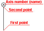 A number of the axis is proposed according to the settings in the default style; while inserting the axis, you may enter any number (each following one will be inserted according to the specified numbering). You can modify the axis number using the relevant option from the context menu. Menu: Formwork Drawings > Structural axis Ribbon: ASD - Model > Elements > Workframes > Structural axis Toolbar: Workframes > Structural axis Command line: RBCX_DEF_SYMBOL_AXIS |
|
Planes |
|
|
Plane |
Opens the Definition of planes dialog, where you can define intermediate (horizontal) planes or inclined planes on which elements of a structure model can be defined. Menu: Formwork Drawings > Planes > Plane Ribbon: ASD - Model > Planes > Plane Toolbar: Planes > Plane Command line: RBCX_PLANE_DEF |
|
Attach to plane |
Use this option to attach selected structure elements to an indicated inclined plane. Geometry of structure elements is adjusted to the slope of the inclined plane. Menu: Formwork Drawings > Planes > Attach to plane Ribbon: ASD - Model > Planes > Attach to plane Toolbar: Planes > Attach to plane Command line: RBCX_ATTACH_TO_PLANE |
|
Detach from plane |
Use this option to detach selected structure elements from an indicated inclined plane (the opposite action to the Attach to plane option). The operation results in returning elements to default levels of the reference plane. Menu: Formwork Drawings > Planes > Detach from plane Ribbon: ASD - Model > Planes > Detach from plane Toolbar: Planes > Detach from plane Command line: RBCX_DETACH_FROM_PLANE |
|
Group planes |
Use this option to create a group of planes. The group is regarded as a separate object that lets you define elements of a structure model with a complicated plane geometry (for example, planes of a multi-pitch roof). To create a group of planes, select planes that should belong to the group, and then specify a name of the group of planes. Once created, the group of planes is regarded in the same way as a standard single plane. Menu: Formwork Drawings > Planes > Group planes Ribbon: ASD - Model > Planes > Group planes Toolbar: Planes > Group planes Command line: RBCX_GROUP_PLANES |
|
Ungroup planes |
Use this option to split a group of planes into single separate planes (the opposite action to the Group planes option). Menu: Formwork Drawings > Planes > Ungroup planes Ribbon: ASD - Model > Planes > Ungroup planes Toolbar: Planes > Ungroup planes Command line: RBCX_UNGROUP_PLANES |
|
Import/Export |
|
|
Import structure from Autodesk CBS
|
Use this option to import of a structure model created in the Autodesk® Concrete Building Structures program. Menu: Formwork Drawings > Import\Export > Import structure from Autodesk CBS Command line: RBCX_LOAD_ROBIN_MODEL |
|
Export structure to Autodesk CBS
|
Use this option to open the Autodesk® Concrete Building Structures program and save a structure model in the format of this program. Menu: Formwork Drawings > Import\Export > Export structure to Autodesk CBS Command line: RBCX_SAVE_ROBIN_MODEL |
|
Save model as ACIS solids
|
Use this option to save a structure model as an ACIS solid (as a drawing in a DWG format). Menu: Formwork Drawings > Import\Export > Save model as ACIS solids Ribbon: ASD - Model > Tools >Save model as ACIS solids Command line: RBCX_ACIS_EXPORT |
|
Display |
|
|
Show building |
After you select this option, a whole structure model will display on the screen. Menu: Formwork Drawings > Display > Show building Ribbon: ASD - Model > Display > Show building Toolbar: Display > Show building Command line: RBCX_VIEW_BUILDING |
|
Show active story |
After you select this option, only an active (selected) story of a building will display on the screen. Menu: Formwork Drawings > Display > Show active story Ribbon: ASD - Model > Display > Show active story Toolbar: Display > Show active story Command line: RBCX_VIEW_STOREY |
|
Show only selected elements |
After you select this option, only selected elements of a building will display on the screen. Menu: Formwork Drawings > Display > Show only selected elements Ribbon: ASD - Model > Display > Show only selected elements Toolbar: Display > Show only selected elements Command line: RBCX_VIEW_SELECT_EL |
|
Show elements |
Select this option to open the Filters - element selection dialog; the option is used to define criteria of selecting elements in a structure model. Menu: Formwork Drawings > Display > Show elements Ribbon: ASD - Model > Display > Show elements Toolbar: Display > Show elements Command line: RBCX_VIEW_ELEMENTS |
|
Show planes |
Select this option to open the Manager of plane properties dialog; the option is used for viewing and editing parameters of defined intermediate or inclined planes. Menu: Formwork Drawings > Display > Show planes Ribbon: ASD - Model > Display > Show planes Toolbar: Display > Show planes Command line: RBCX_EDIT_PLANES |
|
Plan of story |
After you select this option, the software automatically creates a plan of a selected story in a building. Menu: Formwork Drawings > Plan of story Ribbon: ASD - Drawings > Create stories > Plan of story Toolbar: Drawings > Plan of story Command line: RBCX_DEF_STOREY_VIEW |
|
Plan of foundation |
After you select this option, the software automatically creates a plan of building foundations. Menu: Formwork Drawings > Plan of foundation Ribbon: ASD - Drawings > Create drawings > Plan of foundations Toolbar: Drawings > Plan of foundations Command line: RBCX_DEF_FOUNDATION_VIEW |
|
Vertical section |
After you select this option, the software automatically creates a vertical section of a structure model. To create a vertical section, indicate lines that intersect a structure model and a section depth. Menu: Formwork Drawings > Vertical section Ribbon: ASD - Drawings > Create drawings > Vertical section Toolbar: Drawings > Vertical section Command line: RBCX_DEF_V_SECTION |
|
Elevation view |
After you select this option, the software automatically creates an elevation view of a structure model. To create an elevation view, indicate lines of the elevation view and a direction of the view. Menu: Formwork Drawings > Elevation view Ribbon: ASD - Drawings > Create drawings > Elevation view Toolbar: Drawings > Elevation view Command line: RBCX_DEF_ELEVATION |
|
3D view |
After you select this option, the software automatically creates a 3D view of a structure model. Menu: Formwork Drawings > 3D view Ribbon: ASD - Drawings > Create drawings > 3D view Toolbar: Drawings > 3D view Command line: RBCX_DEF_VIEW3D |
|
Detail |
Select this option to automatically generate a detail in drawings. This type of drawing can be widely used in the structure documentation which necessitates preparing drawings (using a more accurate scale) of details of the contact between elements or connections of elements. A detail is a specific type of document; it is created based on another document (a source document). It is usually created in relation to the plan (of story or foundation) or the vertical section. A detail drawing inherits all settings from the source document (see also: Job preferences > Detail, Detail Style). To create a detail:
A circle that indicates the detail is drawn in the source document (the document where the detail location was selected). Note: A detail drawing presents elements to the extent limited by the square inscribed in the specified circle.
Names of subsequent details are unique in the project. A detail is added to the list in the Object Inspector pane; it is under the document it was created from. Menu: Formwork Drawings > Detail Ribbon: ASD - Drawings > Create drawings > Detail Toolbar: Drawings > Detail Command line: RBCX_DEF_DETAIL |
|
Element description |
Use this option to describe individual objects in a structure. Descriptions of structure elements are possible in plans (of stories or foundations) and in sections. Menu: Formwork Drawings > Element description Ribbon: ASD - Drawings > Edit drawings > Element description Toolbar: Labels and dimensions > Element description Command line: RBCX_LABEL |
|
Group description |
Use this option to describe defined groups of structure elements; descriptions of groups can be placed in plans (of stories or foundations), views and sections. To describe a group in the drawing, select any edge of the group element (you can select a part of or whole drawing using a window). If an element belongs to several groups, all groups are described. Groups are described according to the style in element description styles. Menu: Formwork Drawings > Group description Ribbon: ASD - Drawings > Edit drawings > Group description Toolbar: Labels and dimensions > Group description Command line: RBCX_GROUP_LABEL |
|
Dimensions |
|
|
Group dimension line |
Use the Group dimension line option to create dimension lines for structure elements displayed in created plans or sections of a designed object. Indicate elements to be dimensioned and define an offset of a dimension line from dimensioned elements. The software automatically recognizes selected elements and appropriately groups dimension lines. Menu: Formwork Drawings > Dimension lines > Group dimension line Ribbon: ASD - Drawings > Edit drawings > Group dimension line Toolbar: Labels and dimensions > Group dimension line Command line: RBCX_DIM_GROUP |
|
Simple dimension line |
Use the Simple dimension line option to create dimension lines for individual structure elements located in generated plans or sections of a designed object. Indicate an element(s) to be dimensioned (intersect the element with an auxiliary line) and define an offset of a dimension line from the dimensioned element. Menu: Formwork Drawings > Dimension lines > Simple dimension line Ribbon: ASD - Drawings > Edit drawings > Simple dimension line Toolbar: Labels and dimensions > Simple dimension line Command line: RBCX_DIM_SIMPLE |
|
Arc dimension line |
Use the Arc dimension line option to create dimension lines for arc-shaped structure elements (walls, beams, continuous footings) located in generated plans or sections of a designed object. Indicate one arc element to be dimensioned and define an offset of a dimension line from the dimensioned element. Menu: Formwork Drawings > Dimension lines > Arc dimension line Ribbon: ASD - Drawings > Edit drawings > Arc dimension line Toolbar: Labels and dimensions > Arc dimension line Command line: RBCX_DIM_ARC |
|
Add division point |
Use this option to modify dimension lines created by the program by defining additional points (auxiliary lines) to which a given dimension will refer. Dimensions displayed on the dimension line will be recalculated and adjusted to the location of a new point on the dimension line (see the drawing below). Before adding a line 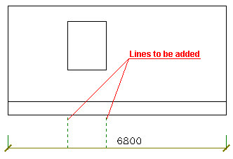 After adding a line 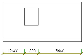 Menu: Formwork Drawings > Dimension lines > Add division point Ribbon: ASD - Drawings > Edit drawings > Add division point Toolbar: Labels and dimensions > Add division point Command line: RBCX_DIM_UTIL_ADD |
|
Delete division point |
Use this option to modify dimension lines created by the software by deleting indicated points (auxiliary lines) on a dimension line. After a point (auxiliary line) is deleted from a dimension line, dimensions on the line will be recalculated (see the drawing below). Before deleting a line 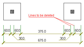 After deleting a line  Menu: Formwork Drawings > Dimension lines > Delete division point Ribbon: ASD - Drawings > Edit drawings > Delete division point Toolbar: Labels and dimensions > Delete division point Command line: RBCX_DIM_UTIL_DEL |
|
Insert elevation mark |
Use this option to insert an elevation mark in a selected place in a drawing. Symbols are drawn according to a default style specified in the Styles of symbols dialog. To insert an elevation mark in a drawing:
Levels are designated with respect to the base level defined in the Building parameters dialog. Menu: Formwork Drawings > Insert elevation mark Ribbon: ASD - Drawings > Edit drawings > Insert elevation mark Toolbar: Labels and dimensions > Insert elevation mark Command line:RBCT_DEF_SYMBOL_COTE |
|
Insert elevation mark in plan |
The option is used to insert an elevation mark in a selected place in a drawing. Symbols are drawn according to a default style set in the Styles of symbols dialog. Menu: Formwork drawings > Insert elevation mark in plan Ribbon: ASD - Drawings > Edit drawings > Insert elevation mark in plan Toolbar: Labels and dimensions > Insert elevation mark in plan Command line: RBCX_DEF_SYMBOL_LEVEL |
|
Insert symbol of main direction |
Use this option to insert a symbol of main direction for slabs. Symbols are drawn according to a default style set in the Styles of symbols dialog. You can perform this operation in the Edition Layout. Menu: Formwork Drawings > Insert symbol of main direction Ribbon: ASD - Drawings > Edit drawings > Insert symbol of main direction Toolbar: Labels and dimensions > Insert symbol of main direction Command line: RBCX_SLAB_MAIN_DIR |
|
Insert opening symbol in view |
Use this option to insert an opening symbol at a selected place in a drawing. Symbols are drawn according to a default style specified in the Styles of symbols dialog. To insert an opening symbol in a view, select the option: Menu: Formwork Drawings > Insert opening symbol in view Ribbon: ASD - Drawings > Edit drawings > Insert opening symbol in view Toolbar: Labels and dimensions > Insert opening symbol in view Command line: RBCT_DEF_SYMBOL_HOLE |
|
Insert opening symbol in cross-section |
Use this option to insert an opening symbol in a cross-section. Symbols are drawn according to a default style specified in the Styles of symbols dialog. Menu: Formwork Drawings > Insert opening symbol in cross-section Ribbon: ASD - Drawings > Edit drawings > Insert opening symbol in cross-section Toolbar: Labels and dimensions > Insert opening symbol in cross-section Command line:RBCT_DEF_SYMBOL_HOLECAST |
|
Select labels and dimensions |
Opens the Filters - element selection dialog, where you can define criteria for selection of labels and dimensions of structure objects. Labels (descriptions) of structure elements are available in plans (of stories or foundations) and in sections. Menu: Formwork Drawings Select labels and dimensions Ribbon: ASD - Drawings > Edit drawings > Select labels and dimensions Toolbar: Labels and dimensions > Select labels and dimensions Command line: RBCX_LABEL_SELECT |
|
Change size of labels and dimensions |
Use this option to specify a scale factor for labels and dimensions of structure objects. After you select a label or dimension of a structure element, define a factor value by which the size of a label or dimension will be multiplied. The option is available in the edition layout. Menu: Formwork Drawings > Change size of labels and dimensions Ribbon: ASD - Drawings > Edit drawings > Change size of labels and dimensions Toolbar: Labels and dimensions > Change size of labels and dimensions Command line: RBCX_MOD_LABEL_SCALE |
|
Tables |
|
|
Elements - Summary |
After you select this option, the element summary table is inserted in a drawing. This table may be inserted for:
Note: The table may be added only to a completed printout (generated drawing); it cannot be inserted to a structure model or to the edit layout.
Menu: Formwork Drawings > Tables > Elements - Summary Ribbon: ASD - Drawings > Tables > Summary of elements Toolbar: Tables > Elements - Summary Command line: RBCX_LIST_ELEM |
|
Costs - Summary |
After you select this option, the summary table of element costs is inserted in a drawing. This table may be inserted for:
Note: The table may be added only to a completed printout (generated drawing); it cannot be inserted to a structure model or to the edit layout.
Menu: Formwork Drawings > Tables > Costs - Summary Ribbon: ASD - Drawings > Tables > Costs - Summary Toolbar: Tables > Costs - Summary Command line: RBCX_LIST_PRICE |
|
Elements - Detailed summary |
After you select this option, the detailed element table is inserted in a drawing. This table includes both summary tables and may be inserted for:
Note: The table may be added only to a completed printout (generated drawing); it cannot be inserted to a structure model or to the edit layout.
Menu: Formwork Drawings > Tables > Elements - detailed summary Ribbon: ASD - Drawings > Tables > Elements - detailed summary Toolbar: Tables > Elements - detailed summary Command line: RBCX_LIST_DETA |
|
Openings - Detailed summary |
After you select this option, a detailed table of openings is inserted in a drawing. This table may be inserted for:
Note: The table may be added only to a completed printout (generated drawing); it cannot be inserted to a structure model or to the edition layout.
Menu: Formwork Drawings > Tables > Openings - detailed summary Ribbon: ASD - Drawings > Tables > Openings - detailed summary Toolbar: Tables > Openings - detailed summary Command line: RBCX_LIST_HOLE |
|
Groups - Summary |
Select this option to insert to a drawing a summary table for a specified selection of groups or for all groups. A summary table includes basic data for a group, such as a volume or area of the group as a whole. Menu: Formwork Drawings > Tables > Groups - summary Ribbon: ASD - Drawings > Tables > Groups - summary Toolbar: Tables > Groups - summary Command line: RBCX_LIST_GRSUM |
|
Groups - Summary |
Select this option to insert to a drawing a detailed table for a specified selection of groups or for all groups. A detailed table lists elements of the group and their basic data. Menu: Formwork Drawings > Tables > Groups - Summary Ribbon: ASD - Drawings > Tables > Groups - Summary Toolbar: Tables > Groups - Summary Command line: RBCX_LIST_GRDET |
|
Update table |
After you select this option, the software updates a selected table to reflect changes made in geometry / parameters of a structure model. Menu: Formwork Drawings > Tables > Update table Ribbon: ASD - Drawings > Tables > Update table Toolbar: Tables > Update table Command line: RBCX_LIST_ACT |
|
Table Printout / Export / Edit |
Use this option to print a table or export a table to an *.xls or *.csv format file. Menu: Formwork Drawings > Tables > Table Printout / Export / Edit Ribbon: ASD - Drawings > Tables >Table Printout/Export/Edit Toolbar: Tables >Table Printout/Export/Edit Command line: RBCX_LIST_EXP |
|
Styles |
|
|
Element description styles |
Opens the Description Styles dialog, where you can define styles (format) of description for individual elements of a structure model. Menu: Formwork Drawings > Styles > Element description styles Ribbon: ASD - Drawings > Settings > Styles > Element description styles Command line: RBCX_STYLE_LABEL |
|
Styles - tables |
Opens the Summary tables - style manager dialog, where you can define/modify summary tables for structure model elements. Menu: Formwork Drawings > Styles > Styles - tables Ribbon: ASD - Drawings > Settings > Styles > Styles - tables Command line: RBCX_STYLE_LIST |
|
Styles - graphic symbols |
Opens the Styles of symbols dialog, where you can define styles (format) of symbols displayed in structure drawings (elevation mark, structural axis symbol). Menu: Formwork Drawings > Styles > Styles - graphic symbols Ribbon: ASD - Drawings > Settings > Styles > Styles - graphic symbols Command line:RBCT_DEF_SYMBOL_STYLE. |
|
Styles - element graphic display |
Opens the Structure model - graphic representation of elements dialog, where you can define the manner of representing structure model elements on the screen (such as line thickness, line type, and colors). Menu: Formwork Drawings > Styles > Styles - element graphic display Ribbon: ASD - Model > Settings > Styles > Styles element graphic display Command line: RBCX_STYLE_GRAPHIC_PRESENTATION |
|
Styles - drawing templates |
Opens the Drawing template manager dialog, where you can determine a method of creating formwork drawings of elements of a building structure. Menu: Formwork Drawings > Styles > Styles - drawing templates Ribbon: ASD - Drawings > Settings > Styles > Styles - drawing templates Command line: RBCX_DRAWING_LAYOUT_MNGR |
|
Databases |
|
|
Section database |
Opens the Section list dialog, where you can:
Menu: Formwork Drawings > Databases > Section database Ribbon: ASD - Drawings > Settings > Databases > Section database Command line: RBCX_TOOL_BASE_SECT |
|
Material database |
Opens the Material list dialog, where you can:
Menu: Formwork Drawings > Databases > Material database Ribbon: ASD - Drawings > Settings > Databases > Material database Command line: RBCX_TOOL_BASE_MAT |
|
Spread footing database |
Opens the Spread footing list dialog, where you can:
Menu: Formwork Drawings > Databases > Spread footing database Ribbon: ASD - Drawings > Settings > Databases > Spread footing database Command line: RBCX_TOOL_BASE_SOLID |
|
Stairs database |
Opens the List of stairs dialog, where you can:
Menu: Formwork Drawings > Databases > Stairs database Ribbon: ASD - Drawings > Settings > Databases > Stair database Command line: RBCX_TOOL_BASE_SOLID |
|
Prefabricated element database |
|
|
Beam database |
Opens the Prefabricated beam list dialog, where you can:
Menu: Formwork Drawings > Databases > Prefabricated element database > Beam database Ribbon: ASD - Model > Settings > Databases > Beam database Command line: RBCX_TOOL_BASE_PREF_BEAM |
|
Column database |
Opens the Prefabricated column list dialog, where you can:
Menu: Formwork Drawings > Databases > Prefabricated element database > Column database Ribbon: ASD - Model > Settings > Databases > Column database Command line: RBCX_TOOL_BASE_PREF_COL |
|
Slab database |
Opens the Prefabricated slab list dialog, where you can:
Menu: Formwork Drawings > Databases > Prefabricated element database > Slab database Ribbon: ASD - Model > Settings > Databases > Slab database Command line: RBCX_TOOL_BASE_PREF_SLAB |
|
Wall database |
Opens the Prefabricated wall list dialog, where you can:
Menu: Formwork Drawings > Databases > Prefabricated element database > Wall database Ribbon: ASD - Model > Settings > Databases > Wall database Command line: RBCX_TOOL_BASE_PREF_WALL |
|
Ground beam database |
Opens the Prefabricated ground beam list dialog, where you can:
Menu: Formwork Drawings > Databases > Prefabricated element database > Ground beam database Ribbon: ASD - Model > Settings > Databases > Ground beam database Command line: RBCX_TOOL_BASE_PREF_GROUND_BEAM |
|
Continuous footing database |
Opens the Prefabricated continuous footing list dialog, where you can:
Menu: Formwork Drawings > Databases > Prefabricated element database > Continuous footing database Ribbon: ASD - Drawings > Settings > Databases > Continuous footing database Command line: RBCX_TOOL_BASE_PREF_CONT_FOOT |
|
Raft foundation database |
Opens the Prefabricated raft foundation list dialog, where you can:
Menu: Formwork Drawings > Databases > Prefabricated element database > Raft foundation database Ribbon: ASD - Model > Settings > Databases > Raft foundation database Command line: RBCX_TOOL_BASE_PREF_SLAB_FOUNDATION |
|
Window database |
Opens the Window list dialog, where you can:
Menu: Formwork Drawings > Databases > Window database Ribbon: ASD - Model > Settings > Databases > Window database Command line: RBCX_TOOL_BASE_WINDOW |
|
Door database |
Opens the Door list dialog, where you can:
Menu: Formwork Drawings > Databases > Door database Ribbon: ASD - Model > Settings > Databases > Door database Command line: RBCX_TOOL_BASE_DOOR |
|
Remaining openings |
Opens the Opening list dialog, where you can:
Menu: Formwork Drawings > Databases > Remaining openings Ribbon: ASD - Model > Settings > Databases > Remaining openings Command line: RBCX_TOOL_BASE_OPENINGS |
|
Tools |
|
|
Modify |
Use this option to modify parameters of a selected structure element (such as parameters of a wall, beam, or column). After the structure element is selected, the dialog displays, where you can modify parameters of the structure element definition (such as material, geometric parameters, and priority). Menu: Formwork Drawings > Tools > Modify Ribbon: ASD - Model > Tools > Modify Toolbar: Tools > Modify Command line: RBCX_MOD |
|
Modify graphical parameters |
Use this option to modify graphic parameters of a selected structure element. After the structure element is selected, the dialog displays, where you can modify parameters of the structure element presentation (such as type of the element contour line, filling, and element hatching). Menu: Formwork Drawings > Tools > Modify graphical parameters Ribbon: ASD - Model > Tools > Modify graphical parameters Toolbar: Tools > Modify graphical parameters Command line: RBCX_MOD_PROP |
|
Element selection by type |
Opens the Filters - element selection dialog, where you can define criteria of selection of elements in a structure model. Menu: Formwork Drawings > Tools > Element selection by type Ribbon: ASD - Model > Elements > Element selection by type Toolbar: Tools > Element selection by type Command line: RBCX_TOOL_SELECT_EL |
|
Element selection by section |
Opens the Filters - element selection dialog, where you can define criteria of selection of elements in a structure model. Menu: Formwork Drawings > Tools > Element selection by section Ribbon: ASD - Model > Tools > Element selection by section Toolbar: Tools > Element selection by section Command line: RBCX_TOOL_SELECT_EX |
|
Element info |
Use this option to display information concerning an indicated element. After an element is selected, the dialog displays, showing basic information about the selected element (such as element type, position, material, length, and priority). Menu: Formwork Drawings > Tools > Element info Ribbon: ASD - Model > Tools > Element info Toolbar: Tools > Element info Command line: RBCX_TOOL_INFO |
|
Select group |
Use this option to select a group in a structure model. selecting a group or groups highlights them in the structure model. After selecting this option, select a selection mode in the command line: selecting a group or selecting elements of the group. It activates the mode of operation on the group (such as adding an element) or mode of operation on elements (such as positioning the elements), respectively. Menu: Formwork Drawings > Tools > Select group Ribbon: ASD - Model > Tools > Select group Toolbar: Tools > Select group Command line: RBCX_SELGROUP |
|
Refresh model |
Use this option to generate a correct structure model and to delete incorrect items in the model that are associated with connections in a structure model element (such as intersections of walls with beams / slabs). Note: After performing this operation all documents (story plans, sections of a building, elevation views, 3D views) are out of date. They need to be generated again, because elements of a structure model might have been changed.
Menu: Formwork Drawings > Tools > Refresh model Ribbon: ASD - Model > Tools > Refresh model Toolbar: Tools > Refresh model Command line: RBCX_MODELREFRESH |
|
Modify |
|
|
Change beam to ground beam |
Using this option, you can swap:
After you change beam types, all parameters determined for a beam/ground beam (section, position with respect to a story) are maintained; only the object type changes. Note: If a beam / ground beam has been positioned, the element should be repositioned after a swap.
Menu: Formwork Drawings > Modify > Change beam to ground beam Ribbon: ASD - Model > Tools > Change beam to ground beam Toolbar: Tools > Change beam to ground beam Command line: RBCX_TOOL_SWAP_BEAM |
|
Copy / Move elements |
Use this option to copy or move selected structure elements to a new location. The Copy / Move selected elements dialog displays. Menu: Formwork Drawings > Modify > Copy / Move elements Ribbon: ASD - Model > Modify > Copy / Move elements Toolbar: Modify > Copy > Move elements Command line: RBCX_TOOL_COPYOBJECTS |
|
Define opening in a beam |
Use this option to define an opening in a beam, a ground beam, or a continuous footing. To define an opening:
Menu: Formwork Drawings > Modify > Define opening in a beam Ribbon: ASD - Model > Modify > Define opening in a beam Toolbar: Modify > Define opening in a beam Command line: RBCX_TOOL_HOLE_BEAM |
|
Cut beam/wall to polyline |
Use this option to cut a beam, a ground beam, a continuous footing, or a wall to the plane determined by a polyline:
Menu: Formwork Drawings > Modify > Cut beam/wall to polyline Ribbon: ASD - Model > Modify > Cut beam/wall to polyline Toolbar: Modify > Cut beam/wall to polyline Command line: RBCX_TOOL_CUT_POLYLINE |
|
Inclination of slab surface |
Select this option to define inclination of a slab. Using it you can dimension slabs of varying thickness (previous versions of the software allowed defining slabs of only constant thickness). To define inclination of a slab:
An offset value is specified in work units. An offset with the [+] sign is directed up (in relation to the building), while the offset with the [-] sign is directed down. Offsets of edges or vertexes of the slab are treated as machinings of the slab. They are saved in Object Inspector on the Parts Edition tab. Offsets can be deleted from the slab to restore its initial thickness. Menu: Formwork Drawings > Modify > Inclination of slab surface Ribbon: ASD - Model > Modify > Inclination of slab surface Toolbar: Modify > Inclination of slab surface Command line: RBCX_TOOL_INCLINED_PLATE |
|
Merge elements |
Use this option to merge elements. To merge elements, select elements to be merged into one element. After performing this operation, the merged elements are deleted from Object Inspector and a new element consisting of component elements displays in their place. The following conditions must be satisfied to perform this operation:
Menu: Formwork Drawings > Modify > Merge elements Ribbon: ASD - Model > Modify > Merge elements Toolbar: Modify > Merge elements Command line: RBCX_TOOL_MERGE_ELEMENTS |
|
Split elements |
Use this option to split an element. To do it, select an element to be split; it can be a linear element or slab. For a linear element, select a division point, and for a slab, define a division line.
Note: After performing this operation, positions assigned to elements that are split, are deleted (if element positioning has been performed previously).
Menu: Formwork Drawings > Modify > Split elements Ribbon: ASD - Model > Modify > Split elements Toolbar: Modify > Split elements Command line: RBCX_TOOL_SPLIT_ELEMENT |
|
Job Preferences |
Opens the Job Preferences dialog, where you can adopt basic parameters used in Autodesk AutoCAD Structural Detailing (such as codes, units, and materials). Menu: Formwork Drawings > Job Preferences Ribbon: ASD - Drawings > Settings > Job Preferences Toolbar: Tools > Job Preferences Command line: RBCX_JOB_PREF. |
|
Preferences |
Opens the Options dialog, where you can specify parameters of the work environment of Autodesk AutoCAD Structural Detailing. Menu: Formwork Drawings > Job Preferences Ribbon: ASD - Drawings > Settings > Preferences Toolbar: Tools > Preferences |
|
Object Inspector - Show / Hide |
Use this option to switch on / off the display of the Object Inspector dialog that, by default, is located on the left part of the screen. Menu: Formwork Drawings > Object Inspector - Show / Hide Command line: RBCTOI |