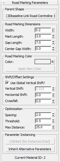
Provides controls for linear road-marking objects.
You can create linear road-marking objects using the Road Markings Style Editor.

Parent Shape group
- [parent shape button]
- Displays the name of the current parent shape for the road-marking object. Click to choose an alternative parent shape. Civil View updates the road-marking object.
Road Marking Dimensions group
- Width
- Sets the width of the road-marking line.
- Mark Length
- Sets the length of each individual mark in broken road-marking lines. For continuous marking lines, this value is ignored.
- Gap Length
- For broken road-marking lines, sets the length of the gap between individual marks. Setting this value of zero creates a continuous road-marking line.
- Center Gap Width
-
Sets the width of the longitudinal gap in the centre of each road-marking line. Lets you create double road-marking lines using a single road-marking object. The width of each double line is half of the difference between the overall road-marking Width and the Center Gap Width.
Road Marking Color group
- Color
- Click the color swatch to open the Color Selector and choose a new color for the road-marking line.
- "R" button: Reset Color
- Click to reset the color of the road-marking line back to the default color specified on the Civil View Preferences panel.
- Apply New Colour
- Click to update the road-marking line to use the new color.
Shift/Offset Settings group
- Use Global Vertical Shift?
- When on, uses the global Vertical Shift setting.
When a road marking is draped across a ground surface, to be visible it must be raised above the underlying surface slightly. The Scene Settings rollout has a global setting for this. Occasionally, individual road-marking objects need to be raised by a greater amount to cater for unusual contours in the underlying ground surface. When this happens, turn off Use Global Vertical Shift, and set a local value.
Note: In Civil View, shadow casting is automatically disabled for all road-marking objects. Even though road markings are always a small distance above the underlying ground surface, they don't cast shadows.- Vertical Shift Set a local vertical shift value for the road-marking object. Disabled unless you turn off Use Global Vertical Shift.
- Horizontal Shift
- Sets a horizontal offset for the road-marking object, relative to the parent shape.
- Crossfall
- Tilts the road-marking object so it can match the crossfall of the underlying road surface. This should be required only in cases where extreme rates of crossfall exist on the underlying road surface.
Optimization group
In general, you shouldn't change these settings. The default values provide the best compromise between smooth-looking road markings and geometric simplicity. They keep the face count in the scene as low as possible. However, occasionally an individual road-marking object might display undesirable geometric characteristics that you can improve by overriding the defaults.
A good example of this is where road markings are placed over a very tight radius and the resulting geometry does not smoothly follow the curve. In this case, more complexity in the road marking geometry is required, and specific optimization values can overcome the problem.
Alternatively, it might be necessary to decrease the face count of a specific road-marking object to remove unnecessary complexity in its geometry. This can decrease rendering time for your visualization.
- Spacing / Threshold
- The Spacing value sets the basic vertex interval along the path of the parent shape. The Threshold value sets the required tangent angle between adjacent sets of vertices along the path of the parent shape.
At each Spacing interval, the tangent of the parent shape at that point is compared with the tangent at the previous point. If the angle in degrees between these two tangents is larger than the Threshold angle, Civil View creates a set of vertices. If the angle is less, Civil View moves on to the next Spacing interval and compare angles again. Once the angle is exceeded, it creates a set of vertices and the process starts again until the end of the shape is reached.
- Max[imum] Distance
-
The maximum distance over which a set of vertices must be created. This comes into effect if the Spacing and Threshold values do not allow for a set of vertices to be created over a distance less then or equal to this value. This can be useful over very long stretches of almost straight road where slight changes in horizontal curvature or vertical alignment are not detected by the Spacing and Threshold parameters.
Tip: The default Civil View settings for road marking optimization, Spacing, Threshold, and Max Distance, are stored in the main civilview.ini file. This file is saved in the /plugcfg folder (there is a copy of this folder for each of the languages used by 3ds Max Design). You can edit the INI file if you need to.
Parameter Instancing group
Allows the parameters of a collection of objects of the same basic type to be shared or instanced.
See Parameter Instancing for further details.