|
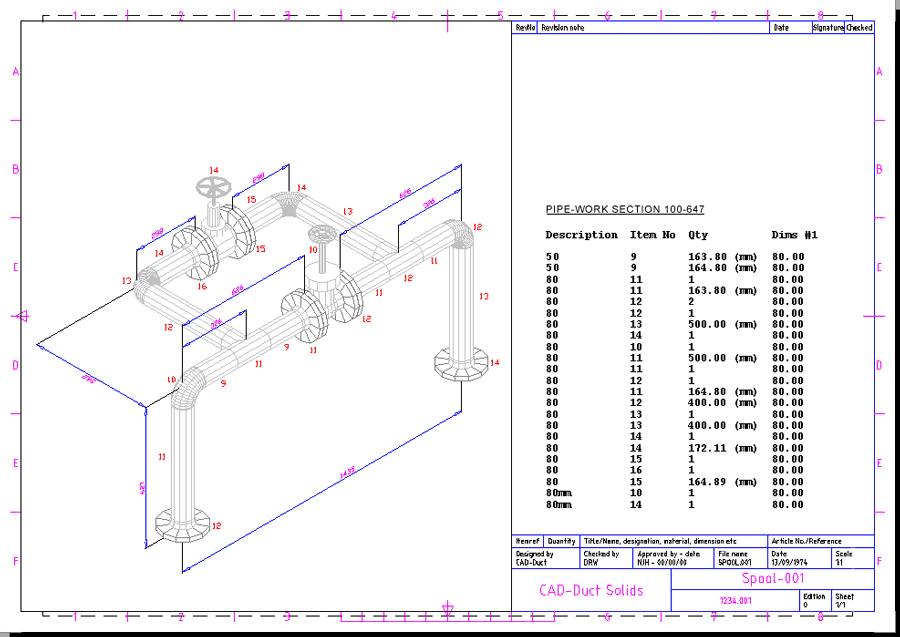
CADmep allows the creation of Spool drawings, users are able to select a drawing template, import the required duct or pipe-work system in sections, providing detailed item and dimension information.
Procedure
- Open the required CAD-Duct/CAD-Mech drawing.
- Type the spooldwg command to prompt the spool dialogue.
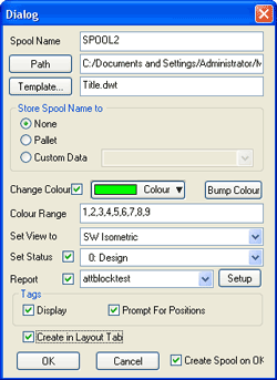
- Enter a Spool Name.
- Path button - specify a location to save the spool drawing.
- Template button - choose a Drawing Template to use with the spool drawing (*.dwt).
- Store Spool Name to:
- None - Default
- Pallet - Stores the Spool Name to the Items Item Entry
- Custom Data - Stores the Spool Name to the Custom Data field
- Change Colour - Check to enable the following options:
- Colour - Select the colour of the duct/pipe-work section
- Colour Range - Sets the AutoCAD Colours in use
- Bump Colour - Click to increment the colour selection
- Set View - Select the view for the Spool drawing.
- Set Status - Sets the Item Statuses for the spooled drawing.
- Report - Select a stored Item Report or use Setup button to configure new reports.
-
Tags:
- Display - Option to display Item Numbers tags
- Prompt For Positions - prompts the position of Item numbers as soon as the model is spooled
- Create in Layout Tab - If not checked the spooled model remains in model space.
-
Create Spool on OK:
- Check to create the spool drawing.
- Leave un-checked if you wish to change settings and update an existing spool.
- Once the above options have been selected Click OK.
- Select the required duct/pipe-work section. Note: When using the Report option, the prompt for report placement is relative to the bottom left-hand corner of the report.