Design Line Toolbar
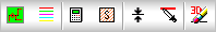
 - New Design Line - Selected for the start of a new Design Line. Active design lines when this is selected will become inactive and grey out. Users should double click Design Lines to re-activate them.
 - Constraint Manager - Used to alter dimensions of an existing line. The Constraints Manager allows selection of Constraint Name, Thickness of the line being drawn, Colour of the line, Shape and Size if requiring to transfer Rectangular to Round sizes and also where you can change the Velocity of the Line if using Constraint entry. Please see the Constraint Manager for further information on the functions within this dialogue.
 - Flow/Size calculator - Tool for assistance with calculations for such things as Fluid, Velocity and Shape changing. Please read more information about this tool from the Flow Calculator Help Topic.
 -Ductulator - Section Flows can be obtained and reviewed using this toolbar option.
 - Pick Elevation - Enables selection of an existing line which therefore populates the Entry dialogue elevation field automatically based on the selected lines elevation.
 - Pick Constraint - Used for selecting an existing lines properties that are required to enter a similar size and elevation.
 - Erase 3D Design - Filled in 3D objects are removed so only the design line exists.
Activated Design Line Menu

Line Menu
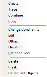
- Create: Initiates the command to start a new line inside of the existing Design Line. Prompts for Select Start Point and awaits Left click of first point to start drawing.
- Trace: Allows selection of a line in the drawing which is to be converted to a Design Line.
- Combine: Prompts for selection of two Design Lines in which will merge into one. Inactive lines can be merged together and filled together.
- Copy: Prompts for Line selection. A single Base point of the selection is made and then Offset accordingly to generate the 'copy of' lines. Can be used for full branches that include node placement (e.g. Copying Multiple lines that contain Terminals and In line equipment), in which all are duplicated when the Offset is specified. The following procedures can be used for copying lines:
- Window selection Top Left to Bottom Right - Selects only the lines that are within the window region. Right Click to confirm selection.
- Window selection Bottom Right to Top Left - Selects all lines touched by the window selection. Right Click to confirm selection.
- Left Click on each Line - Allows selection of individual lines, each left click adds tot he selection. Right Click to confirm selection.
- Change Constraints: opens up the individual Constraints Manager view for adjusting Constraint, Line, Shape and Size information.
- Edit: opens up the Line Editor for changing Constraints of the Line, Size and Elevation to name the most common. Please view the Line Editor for more information on what this feature offers.
- Offset: Prompts for selection of two points where the line can offset a distance entered away from the line
- Elevation: Prompts for selection of two points where the Elevation can be entered using the entry box that appears after the second selection has been made. The two points are raised or lowered to the new value entered independently with the required Riser lines on each of the points.
- Drainage Tool: Opens up the Drainage application for configuring Public Health Drop into Fall runs. More information can be viewed from the Drainage Tool Help Topic.
- Delete: Prompts for selection of line(s) that are required for deletion. After using one of the selection types listed below, Right Click confirms deletion.
- Window selection Top Left to Bottom Right - Selects only the line(s) that are within the window region. Right Click to confirm selection.
- Window selection Bottom Right to Top Left - Selects all line(s) touched by the window selection. Right Click to confirm selection.
- Left Click on each Node - Allows selection of individual lines, each left click adds to the selection. Right Click to confirm selection.
- Break: Line Break is to separate a single design line into two or more separate design lines, could be used when a design line is getting too big, or you are happy with an area, break so it does not fill again as you work with the unfinished area.
- Dependant Objects: Allows selection of alternative Design Lines that are inactive, which are required to be filled when the active Design Line is also filled.
Dependent Objects "associate" 1 design line with another, for instance Design line A (supply) and Design Line B (extract) if you make B dependent on A, when you fill in 3D A, B will also fill in, but if you fill in B, A will not, it also carries over the Flow from one to the other.
Node Menu
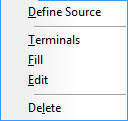
- Define Source: Prompts for a selection of an end node where the flow will be set to/from. A Calculate with automatically update the arrow indicators for the flow.
- Terminals: Opens up the Terminals dialogue which can be used to preset Terminal Size, Flow Rate and Elevation values of the node placed into the drawing. Please view the Design Line Terminals for further information on this dialogue.
- Fill: Fills amended nodes only after replacements have been made on the Design Line.
- Edit: Opens up the Node Editor for editing the constraints of the Node. Please view the Design Line Node Editor Help Topic for further information.
- Delete: Prompts for selection of the nodes to delete, after using one of the selection types listed below, Right Click confirms deletion.
- Window selection Top Left to Bottom Right - Selects only the nodes that are within the window region. Right Click to confirm selection.
- Window selection Bottom Right to Top Left - Selects all nodes touched by the window selection. Right Click to confirm selection.
- Left Click on each Node - Allows selection of individual nodes, each left click adds to the selection. Right Click to confirm selection.
Template Menu

- Insert: Provides a selection of existing Templates for insertion onto the active Design Line. The insertion point is use for placing the template scenario into the Viewer.
- Save: Allows selection of the active Design Line insertion point. The confirmation of the insertion point prompts the user to save a Template of the active Design Line for use to create multiples within that actived line or inserted into a new design line containing a replica scenario.
- Manage: Provides the user woth the ability to delete or rename existing templates.
View Menu
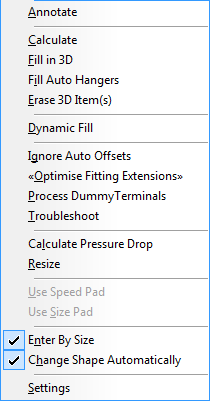
- Annotate: Displays all Line and Node annotation on the drawing which can be configured from the View menu, Settings selection.
- Calculate: Refreshes all Line and Nodes in the active Design Line. Recommended for when changing Service information such as Flow Direction or Change constraints. Normal practise would be to Calculate and then Fill In 3D.
- Fill in 3D: Used to generate the items of the active Design Line using the Service items currently selected in the view. Fill in 3D will begin to exchange button mappings of the Design Line with Button Codes of the Service Items to generate them for Job Contents and display them in the drawing. Button Mappings not found are further identified from within the Service Button Mappings tab where combinations can be used.
- Fill Auto Hangers: Used to only fill the Hangers for the active Design Line using the Service Support Specification which is used to identify when to visually display the required support and its spacing requirements.
- Erase 3D item(s): Clears the active Design line of 3D objects. (Removes them from the job too).
- Dynamic Fill: Automatically generates the items as you draw the Design Lines.
- Ignore Auto Offsets: Used to force the manual Offset rules from the Service Setup
 Offset Rules tab. Using this option will logically preset and calculate the Offsets unless set to Ignore.
 - Optimise Fitting Extensions:
- Process Dummy Terminals:
- Troubleshoot: Opens up a dialogue and attempts to identify which button mappings did not manage to succeed and where the issues are after the Fill has been performed.
- Process Dummy Terminals: The ability to create a terminal from a node point.
- Calculate Pressure Drop: Opens the Pressure Drop dialogue which can be used to verify flows and velocities of each section run. More information can be obtained from the Design Pressure Drop Breakdown Help Topic.
- Resize: Used to map sizes of one service to another as the dimensional data may vary. Common with Copper sizes and Resizing to Steel sizes. Please view the Design Line Resize for further information on how this can be achieved.
- Enter by Size: Allows the user to switch the entry method when using Design Line. Size entry or Constraint entry. See Design Line Takeoff for explanations on these.
- Change Shape Automatically: When this option is enabled, this will default the Shape of the Design Line to Round or Rectangular based on the number of dimesions entered. Entering 1 dimesion for Round and 2 for Rectangular. The drop don can be used to specify Oval as an alternative.
- Settings: Opens up the Line and Node settings for the active Design Line. Here you can specify which Annotation is required for the active Design Line. Users wanting to edit the default Settings for the Service should use the Service Design Entry Tab and click the text symbol A from the Right hand toolbar.