Prior to running an Autodesk Simulation CFD analysis, the geometry is broken up into small pieces called elements. The corner of each element is a node. The calculation is performed at the nodes. These elements and nodes make up the mesh.
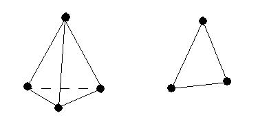
In three dimensional models, most elements are tetrahedrals: a four sided, triangular-faced element. In two dimensional models, most elements are triangles:
Terminology
Solution accuracy depends on a good mesh, and Autodesk Simulation CFD automates much of the mesh creation process to help you create a good mesh for your simulation.
- Automatic Mesh Sizing: A comprehensive topological interrogation of the analysis geometry to determine the mesh size and distribution on every model entity.
- Adaptive Meshing: A technique to progressively improve the mesh definition based on solution results.
- Extrusion Meshing: A way to mesh parts that have a uniform-cross section with multiple layers of wedge (prism) elements.
- Manual Mesh Sizing: User-defined meshing.
- Mesh Enhancement: Automatically add element layers along all fluid-wall and fluid-solid interfaces.
- Geometric Changes: How the mesh distribution is transferred across design iterations.
- Element Descriptions: Technical overview of the available element types.
- Multi-Threaded Meshing: A way to improve meshing performance.