Calculate Ruling Span and Clearance for overhead lines. The analysis operation calculates conductor sag and tensions at normal and worst case conditions using information specified in variables.
If Auto Resolve is selected in the Analysis panel, the Overhead Engineering analysis operations are performed automatically as you create pole and line features. Pole heads with primary, secondary, neutral, are positioned on the pole at the proper levels. Transformers and switches are also positioned at the proper levels. Leveling is determined by the voltage of the conductors attached to the pole heads. Poles and pole heads are sized appropriately.
The required clearance value between devices on the pole and between devices and the pole head can be defined in the ST_OVERHEAD_CLERANCE table and the Pole Attachments rules. Pole Attachments rules are found in the Analysis section of the Rule Configuration dialog box. For more information on Utility Design tables, see To Configure Tables. For more information about rules, see About Rule Points.
As you draw the layout, be sure to use the Connected To icon to establish connectivity between poles, wires, transformers, and switches.
- Click Home tab
 Analysis panelCalculate Sag
  .
. - Click the overhead lines of interest and then press ENTER to perform the analysis.
A trace is performed to locate related features.
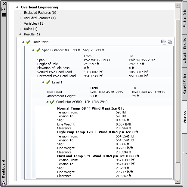
- View the results in the Analysis palette.
- Expand the details for Overhead Engineering.