Use the options on the Diagonals tab to define diagonal (bracing) parameters.
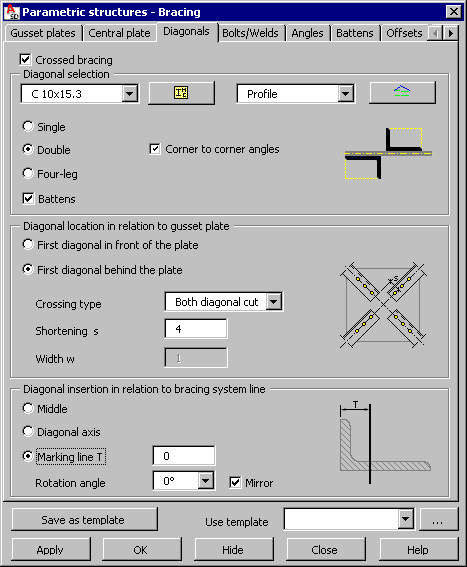
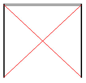
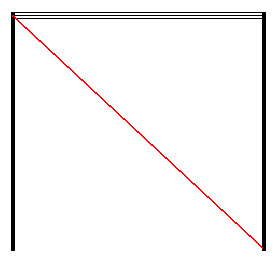
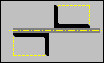
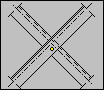
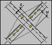
At the top of the dialog is the Crossed bracing option. If this is selected, the bracings are generated as two crossing diagonals; if this option is not selected, only one diagonal is generated (see the drawing below).
crossed bracing not-crossed bracing
Specify parameters of the diagonal profiles:
- Type of profile - profiles available on the selection list are those defined in the Profile List dialog. To add a profile to the list, click
 . The Profile list dialog displays, where you can select a profile. If a tubular profile is selected, the Tubes tab becomes accessible in the Bracing dialog.
 - Profile family to which the diagonals will belong - families available on the selection list are those defined in the Family Manager dialog. To add a family to the list, click
 . The Family manager dialog displays, in which you can select a family.
 - Type of diagonal cross-section
- Single - a diagonal consists of 1 profile
- Double - a diagonal consists of 2 profiles (for example, angles); there are 2 possible ways in which the angles may be positioned with respect to each other
 Angles with legs back to back
 Angles positioned corner to corner (select Corner to corner angles)
o Four leg - a diagonal consists of four profiles (angles)
Options available under Diagonal location in relation to gusset plate:
- First diagonal in front of the plate
- First diagonal behind the plate
- Crossing type (mutual positioning of diagonals):
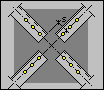 Both diagonals cut
 First diagonal cut
 First diagonal continuous
 Passing diagonals
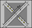
 Passing diagonals (with plate)
 First diagonal cut (with plate)
 First diagonal continuous (with plate)
 First diagonal cut with gusset
 First diagonal continuous with gusset
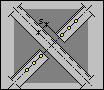
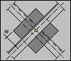
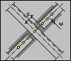
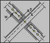
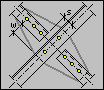
- Parameters of mutual positioning of diagonals (values are displayed symbolically in drawings of individual types of diagonal positioning)
- Shortening s (inaccessible to passing diagonals)
- Plate width w (accessible only to the last two types of diagonal positioning)
Options available under Diagonal insertion in relation to bracing system line (bracing plane):
- Middle - in the center line of the leg of a diagonal profile
- Diagonal axis
- Marking line T - this is a line on which bolts will be positioned, and which is determined by the value T (the distance from the profile edge)
Use Rotation angle and Mirror in order to properly position the diagonal profile in relation to the bracing plane.
After you finish defining diagonal parameters, click the Bolts/Welds tab to display the Bracing - Bolts/Welds dialog.
See also: