You can define a plate girder (beam).
To begin defining a plate girder, open the Beam dialog from:
- Menu: Steel > Plate girders > Beam
- Ribbon: ASD - Model > Elements > Beam
- Toolbar: Plate girders > Beam
 .
.

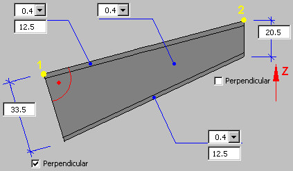
Point 1 is the beginning point of the plate girder (the first point defined in a drawing), and point 2 is the end point of the girder plate. Both points are positioned on the top face of the upper flange in the middle of the flange width.
Click Select new points in order to define a new position for a defined beam (the beam is moved from its current position to the new one).
A generated steel beam may have the following cross-section:
![]() - I-section
- I-section
![]() - T-section
- T-section
Elements in a plate girder (beam):
- For I-beams - 3 plates (web, upper flange, lower flange) and workshop welds
- For T-beams - 2 plates (web, lower flange)
The drawing below displays values that can be defined in the dialog (it is illustrated for an I-beam – some options are not available for a T-beam):
- Thickness and width of the upper flange (these values are constant along the beam length)
- Thickness and width of the lower flange (these values are constant along the beam length)
- Web thickness (this value is constant along the beam length)
- Web height at the beginning and at the end of the plate girder (the definition method depends on the Perpendicular options).

In the upper part of the dialog, select a part family. Part families available on the selection list are those defined in the Family manager dialog. To add a family to the list, click ![]() . The Family manager dialog displays, where you can select a family.
. The Family manager dialog displays, where you can select a family.
Define the beginning and the end of a beam:
- If Perpendicular is selected (at the beam beginning or end), the web plate and the plate of the beam lower flange at the beginning or at the end of the beam are set in the plane perpendicular to the line determined by points P1 and P2 positioned on the beam upper flange (see the drawing below, in which Perpendicular is selected for point 1).
- If Perpendicular is not selected (at the beam beginning or end), the edges of the web plate and plates of beam flanges at the beginning or at the end of the beam are parallel to the Z axis of the local coordinate system (UCS) (see the drawing below, in which Perpendicular is turned off for point 2).
After you finish defining the plate girder dimensions, click the Welds tab to display the Beam - welds dialog.
See also: