You can define geometry of steel stairs.
To begin definitng stairs, open the Stairs dialog from:
- Menu: Steel > Parametric structures > Stairs
- Ribbon: ASD - Model > Parametric structures > Stairs
- Toolbar: Parametric structures > Stairs
 .
.
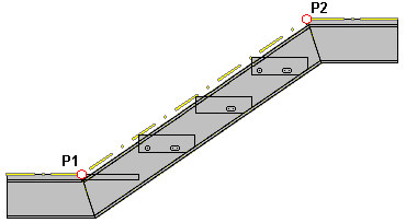
In the drawing area, click to specify the beginning point of stairs and the end point of stairs (definition of points P1 and P2 shown in the figure below).

Define the position of points P1 and P2:
- Notchboard - point P1 is the beginning and point P2 is the end of a notchboard that includes lengths of landings (see the drawing below).

- System line - point P1 is positioned on the lower floor level and point P2 is on the upper floor level, and both points lie at the locations where the system line is broken - (see the drawing below).
Available stair types:
Profiles available on the selection list are those defined in the Profile List dialog. To add a profile to the list, click ![]() . The Profile list dialog displays, where you can select a profile.
. The Profile list dialog displays, where you can select a profile.
Profile families available on the selection list are those defined in the Family Manager dialog. To add a family to the list, click ![]() . The Family manager dialog displays, in which you can select a family.
. The Family manager dialog displays, in which you can select a family.
For Slope angle, the displayed value results from the defined dimensions of stairs (positions of points P1 and P2).
The stair dimensions are defined in the edit fields located in the schematic drawing for the selected type of stairs.
If you select either Lower landing or Upper landing, the respective landing is generated in the defined stairs. If either landing option is selected, the options on the Landing tab become accessible.
For Offset from the definition line, specify an offset of the stairs from the axis determined by the points P1 and P2.
After you finish defining geometry of stairs, click the Step distribution tab to display the Stairs - Step distribution dialog.