Learn how to define types and values of loads for particular load cases.
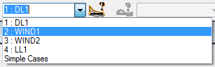
- In the Cases Selection box of the Selection toolbar, expand the Cases drop-down menu and select 2: WIND1.
- Click
 (Loads
  Load Definition...).
The Load Definition dialog opens.
- In the Node tab, click
 (Nodal force).
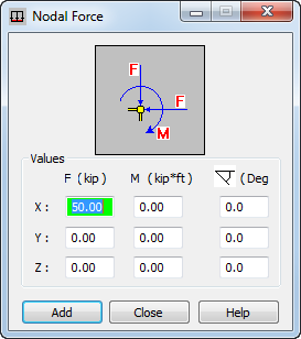
The Nodal Force dialog opens.
- Type value of load 50 in the FX box, and then click Add.
- Place the cursor in the Apply to field, and type "2 4" to select the nodes on which you want to apply a nodal force load.
Alternatively, go to the drawing area, and hold the Ctrl key to select nodes with numbers 2 and 4.
- Click Apply.
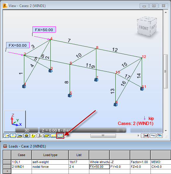
The WIND1 load appears in the drawing area and in the Loads - Case table.
- Click
 (Load value descriptions) at the bottom of the drawing area to display the descriptions of loads values.
- In the Cases Selection box of the Selection toolbar, expand the Cases drop-down menu and select 3: WIND2.
- Go to the Bar tab, and click
 (Uniform load).
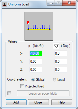
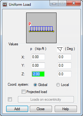
The Uniform Load dialog opens.
- Type value of load -10 in the PX box, and then click Add.
- Place cursor in the Apply to field, and type "13 14" to select columns to which a uniform load will be applied.
Alternatively, go to the drawing area, and hold the Ctrl key to select columns with numbers 13 and 14.
- Click Apply.
The WIND2 load appears in the drawing area and in the Loads - Case table.
- In the Cases Selection box of the Selection toolbar, expand the Cases drop-down menu and select 4: LL1.
- In the Bar tab, click (Uniform load).
The Uniform Load dialog opens.
- Clear PX box, and then type value of load -2 in the PZ box, and then click Add.
- Place cursor in the Apply to field, and type "6 7 11 12" to select columns to which a uniform load will be applied.
Alternatively, go to the drawing area, and hold the Ctrl key to select columns with numbers 6, 7, 11 and 12.
- Click Apply and close Load Definition dialog.
The LL1 load appears in the drawing area and in the Loads - Case table.
- In the Cases Selection box of the Selection toolbar, expand the Cases drop-down menu and select Simple Cases.
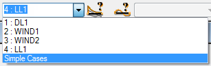
- All defined loads shown below:
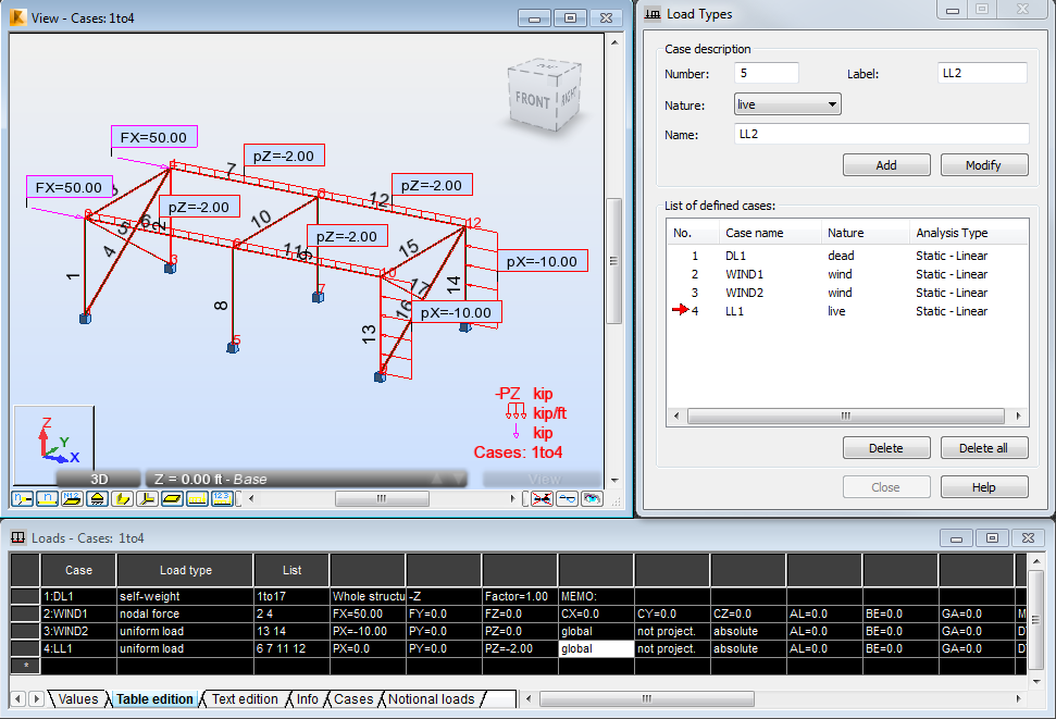 Note: You can use the Loads - Cases table to modify the defined loads. You can change for example the loads types, list of elements which loads are applied and values of these loads. You can also use this table to add new loads to the structure.
 - Save the project as Frame_3D_Loads.rtd.