Autodesk Inventor files have properties called iProperties. They are used to track and manage files, create reports, and automatically update assembly bills of materials, drawing parts lists, title blocks, and other information. Factory assets also have properties very similar to iProperties. These properties can be defined using iProperties or by using the Asset Properties command.
- A property can be entered as text or as a key parameter expression.
- If you update properties, those updates are not applied to assets already placed in your layout. To update placed assets, click Update Assets in the Factory Assets panel on the Factory tab.
- If an asset appears multiple times in a layout, but the properties differ, the asset appears as a single row in the bill of materials.
Complete the following steps to assign properties to an asset.
- On the
Asset Builder tab, in the
Author panel, click
Asset Properties
 to open the properties window.
- Enter
Summary information to help you search for this asset in the Asset Browser. These properties cannot change when you place the asset in a layout.
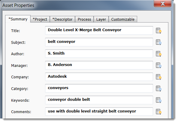
Note: The lightbulb icon that appears next to each field determines if the property value appears on the block in AutoCAD:
Click the icon to turn on the display. Leave the icon turned off to hide the display in AutoCAD.
These icons also appear for the Project and Descriptor fields, and for the Value field on the Customizable tab.
- The
Project tab includes information that is useful when preparing a bill of materials. These properties cannot change when you place the asset in a layout.
File Subtype File type; for example, dwf or ipt Part Number Part number of the asset. If you leave this blank, the file name is automatically assigned as the part number. Stock Number Stock number of the asset Description A brief description of the asset Revision Number File revision number Project Project name Designer Project or model designer Authority Signature authority Cost Center Cost center to apply the asset Estimated Cost Cost of the asset used in the bill of materials and other calculation costs Create Date Today's date; click the calendar icon to select a different date Vendor Manufacturer or supplier name if this is a third-party asset WEB Link Vendor link or other relevant Web site address - Click the
Descriptor tab to add additional information about an asset such as type, part number, flow rate, etc. Unlike an annotation, a descriptor is added when authoring and publishing an asset in the
Asset Builder environment. It cannot change without editing the asset. To view an asset's descriptor in a layout, hover the cursor over the asset.
A published asset can have only one descriptor with optional extended descriptor text. If an asset has variants, click the Advanced button to use an iLogic rule to create a descriptor for each variant.
- Enter
Process tab information to run simulations in Process Analysis 360. If you are not using Process Analysis 360, skip to the Layer tab in the next step.
Process Object Check this box to designate this asset as a simulation object, and then select the object type: Buffer, Processor or Source. The fields that appear vary based on your object type selection. Buffer Buffers temporarily store items produced by a processor. Name: buffer name; for example, storage1
Capacity: how many items the buffer can store
Processor Processors receive source materials or parts and perform operations on them. Name: processor name; for example, base assembly
Description: processor description
MTBF: mean time between failures for this processor and all of its operations; for example, 4400 hr indicates that, on average, this processor will run 4400 hours before failing
MTTR: mean time needed to repair this processor after a failure; for example, 60 min indicates that, on average it will take 60 minutes to repair
Setup Cost Rate: setup expenses divided by the amount of setup time
Processing Cost Rate: processing expenses divided by processing time
Uptime Percentage: percent of time the processor is operating
Energy Consumption Rate: number of items processed per unit of energy
Processor Operation Name: name of the overall process model of which this processor is a part; for example engine assembly
Processing Time: number of items processed in the selected unit of time
Setup Time: time required to set up the processor to perform this operation
Sequential Operations: run the operations in the sequence shown; to add an operation to the list click

Source Sources are raw materials or parts entering a factory workflow. Name: source name; example, metal rod
Output Rate: number of items the source supplies in the selected unit of time
Infinite Feed: indicates that an unlimited supply is available; if supplies are limited, leave this blank, and enter a value in the Total Number of Parts field
Total Number of Parts: number of items available from this source
-
The Layer tab lets you select an existing layer or define a new layer in which to place the asset. Automatic layering is useful if you want to control the visibility of this asset in complex designs.
Select Specify Layer for Asset to associate a layer with this asset. If you do not select this checkbox, the asset will be placed in the current DWG layer in AutoCAD or current layout layer in Inventor.
To create a new layer, type a name in the text box and select a color to represent the layer.
To select an existing layer, choose one from the list that appears. The list shown is pulled from the file designated in the Load Layers from File field on the Asset Builder tab in Factory Options. If no file is designated in the settings, the layer list is blank.Note: You must select the Enable automatic layering check box on the Assets tab in Factory Options to activate this feature. - The
Customizable tab lets you add custom properties to help you track asset data. Information entered here appears on the Factory Properties Palette organized by category:
Name Enter a new custom property name or select an existing custom property for editing. Type Select a data type. Value Enter a value that conforms to the selected data type. Category Enter a new category name or select an existing one. Click Add to add the property to the list. The Delete button deletes the selected property from the properties list.
After you define these properties and publish the asset, you can place it in your AutoCAD and Inventor layouts.
Defining Asset Properties With Key Parameters
As you define asset properties, you can either enter text in the fields or an expression that defines a model parameter. For example, if you add the expression "=The height of the model is <Height>" to the asset properties Description field, the description that appears for an asset in the palette, preview, tooltips, drawings, and exported spreadsheets will include the actual height of the selected asset. So, if an asset is 70 inches tall, the description appears as "The height of the model is 70 in". Expressions and values are also searchable. For example, you can search for "Height is 70 in" or "Height is" or "70 in" to find assets that match that criteria.
Expressions are supported in all of the property fields except the following:
- Process tab properties
- Layer tab properties
- Estimated Cost on the Project tab
- Create Date on the Project tab
Expressions defined for an asset in Inventor also appear with the asset in AutoCAD and Navisworks.
To enter an expression, either type it directly in the field, or click in the field and then click the ellipses (...) to display a multiline entry window.
Expression Format
An expression must begin with an equal sign (=). Anything that follows = is considered part of the expression. To add a key parameter, follow this format <parameter name>. For example, =The width is <width> or =Size is <Length>*<Width>*<Height>.
The parameter name must match a defined parameter name and is case-sensitive. If a parameter name is capitalized, it must be capitalized in the expression as well. To see an asset's key parameters, click the ellipses (...) in the property field to display the multiline entry window, and then click Key Parameters.
Once an asset is published, a user can only modify expressions included in customizable properties or in asset tags.