Inventor Home
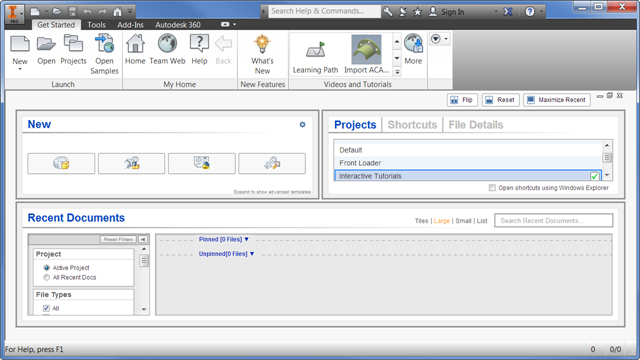
- The panel workspace is customizable.
- Drag the handles to resize the panels.
- Use Flip to reconfigure the panels.
- Use Reset to restore the default layout.
- Use Maximize Recent to fill the space with the Recent Documents panel.
- Presentation files are added to the New file list.
- Click Advanced in the New file panel to access all file templates.
- Vault status is displayed for recent documents.
- Projects, Shortcuts, and File Details tabs are added to Home.
- Click Projects to set the active project file.
- Click Shortcuts to create fast access to project locations, files, and folders.
- Click File Details to view rich file information.
- New filter option allows you to view the information you want in the Recent Documents display.
- Set the Project filter to show only files in the active project, or all recent documents.
- Set the File Types filter to add or remove file types from the display.
- The Sort By filter provides multiple sorting options.
- The Date Modified filters allow you to fine tune the display with a wide range of dates.
Add or remove file types from the display.
- Move your mouse over a file in the Recent Documents list to view the available operations. For example:
- Open the file
- Remove from the list
- Open with options
- Open containing folder
- Explore containing folder
- File details
- Clear unpinned documents Tip: The action to Clear unpinned documents from the recent files list is permanent and cannot be undone. You must open the file again to display in the recent documents list.
- Click Tiles, Large, Small, or List to change the display of the Recent Documents list.
Access Team Web and Online Help
Some proxy servers require authentication before granting access to the internet. If authentication is required, a new dialog box appears that lets you provide a username and password.
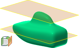
Work Plane
Changes to Content Center Libraries (not available in Inventor LT)
The Content Center libraries are updated to the latest industry standards.
You can now set the maximum length for Structural Steel to 50 m for all libraries. This setting is no longer limited to ANSI.
For complete details on the changes to the Content Center libraries, click here.
Enhancement Updates to Dialog Boxes
The following dialog boxes contain new features:
- Parameters dialog box: A Copy and Paste function is now available within the right-click context menu. The Paste option is available only when there is content copied to the clipboard. The numerical sort order is now based on value rather than the leading digit.
- Link Parameters: This dialog box is now resizable to accommodate extra rows. When you resize this dialog box, the size persists from session to session.
- Thicken/Offset dialog box: The Apply option is added so you can execute multiple operations without exiting the command box.
- Hole dialog box: The Centers option now has a selection counter, displaying in parentheses the number of selections made.
- Punch dialog box: The Centers option now has a selection counter, displaying in parentheses the number of selections made.
- Application Options/General tab: A link is provided in Help options to download the local Help.
-
Resizable dialog boxes: The following dialog boxes are now resizable and persist throughout your session.
- Pack & Go
- Symbol Library
- Boundary Patch
- Edit Balloon (drawings)
- Project Editor
- Link Parameters (parts and assemblies) dialog box
Update to Export Formats for Global Bill of Materials (BOM), Parts Lists, and Revision Tables (not available in Inventor LT)
A new list of acceptable formats to export your Global BOM, parts lists, and revision tables is now available in the drop-down menu.
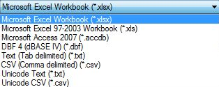
The Access, DBF, Text, CSV, and Unicode exports require Microsoft Access Database Engine to be installed on your computer, which is part of Microsoft Office installation. For 64-bit Inventor, install 64-bit Microsoft Office in order to export these files. If 64-bit Microsoft Office is not installed, the following error message displays:
Changes to Operating System Support (not available in Inventor LT)
Inventor 2016 now supports 64-bit Windows 7, Windows 8, and Windows 8.1 operating systems. Inventor LT also supports 32-bit Windows 7.
All inventor products, except for Inventor LT, no longer offer support for operating systems with 32-bit processors.
Security Enhancements to Add-In Manager (not available in Inventor LT)
When a non-Autodesk product add-in is loaded, a new dialog box displays. You can now choose to Allow or Block an add-in from loading. This setting will be retained for future sessions. You can examine and change the Allow/Block settings using the Add-In Manager.
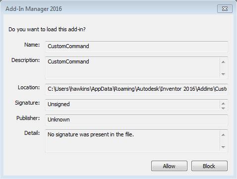
The following three security controls are now available in the Add-In Manager 2016 dialog box:
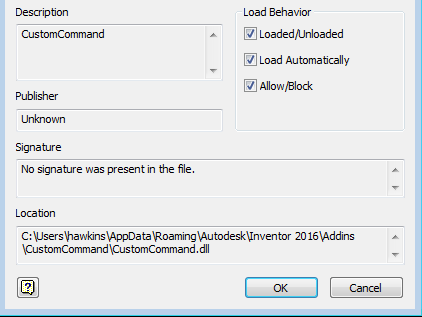
- Allow/Block check box in the Load Behavior area. This box is checked and disabled when Autodesk, Inc. approves the add-in.
- Signature text box shows the add-in is signed and has valid certificates.
- Publisher text box shows the add-in approved by Autodesk, Inc.
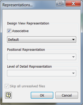
Enhanced Representation Support in Presentations (not available in Inventor LT)
Use the new Representations dialog box to change the current design view and associativity. To access this new dialog box, right-click the Explosion node within your model browser in a Presentation and select Representations.
New Taskbar Menu Options Available for Tiling
Tile Horizontally and Tile Vertically menu options were previously only found in the top ribbon. Now there is convenient access to these options through the taskbar menu found at the bottom left corner of your workspace.

Added Window Select for Faces When Using Delete Face and Thicken Offset
In these commands, you can use a selection window to pick connecting faces of one set of body selections. If a surface body and a solid body are defined, you cannot select faces from both bodies at the same time. After you make the initial selection on a body, you can select more surfaces from the same body.
- Cross selection: Select from right to left. Anything that is 100 percent contained within the selection frame is selected.
- Window selection: Select from left to right. Anything that is partially contained within the selection frame is selected.
Use Keyboard Shortcuts for Select Other
In model views, when you select a component or a subassembly, you can use the shortcut, Ctrl+A for Select Other. This option is listed in the shortcut and command alias reference in the Customize dialog box, Keyboard tab, and View category, where you can customize them.
Dock Inventor Browsers on Any Application or Window Edge
While working with one or more monitors, you can undock and drag any of the Inventor browsers. This can be done with modeling, iLogic (not available in inventor LT), Vault browser, or the Tutorial (Learn) browser. The browsers attach to one another and to any Inventor application edge. They attach either side by side or stacked.
An Always on top context option is available for all detached browsers. Browser positions and settings persist from session to session.
Use Escape (Esc) key to Cancel an Operation
Press the Escape key to abort or cancel an operation in process. The time it takes to cancel an operation may vary depending on the feature or data set that is in use. For operations with realistic preview, such as shell or fillet you can interrupt the preview.
Currently, not all operations are interruptible and some operations do not respond immediately when pressing the Escape key. A message displays when the cancellation is complete.
Copy Parameters to User Parameters
While working with Parameters, you can now copy an existing parameter, including all its settings and multivalues, as a User Parameter. Previously, recreation and manual entry was required for each value.
Import and Export External Rules Configuration for iLogic (not available in Inventor LT)
You can now import/export iLogic configuration settings (as an XML file) to be shared between different users and machines. Once configured, externally mapped folders appear beneath a Standards Directory tree that will update/refresh immediately when content changes (sub folders and rules). In the past, external paths had to be manually added.
External rules configuration settings can also be leveraged and mapped during creation of deployments.
Global forms can now be refreshed through a right-click context option to reflect the most up-to-date form.
New Import and Export SMT File Extension Available for Autodesk Shape Manager (ASM) Files
Autodesk has introduced a new import and export file type associated with ASM files. You can now import and export ASM files using the SMT file extension.
Mockup 360 Now Available from the Inventor App Store
You can now download Mockup 360 from the Inventor App Store. Mockup 360 is no longer available for install from the Inventor installer.
Update to Allow Part Appearance and Body, Feature, or Face Color to be Pushed from Derived Part to New Part
A new Use color override from source component option is available in Derived Assembly, Derived Part, Make Part, and Make Component dialog boxes. This checkbox, when checked, pushes the Part appearance and body, feature, or face color overrides applied to faces from the derived part into the new part. If unchecked, the appearance is set to default.
Example dialog boxes:
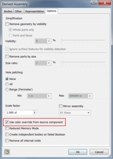
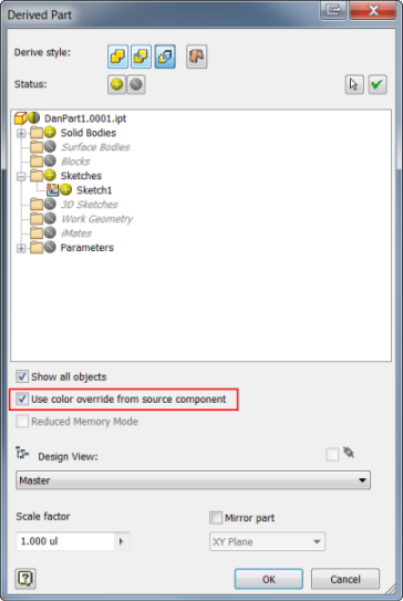
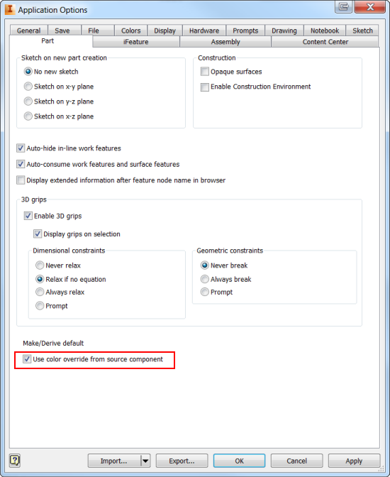
A global setting can be set to default the Use color override from source component check box to remain checked or unchecked throughout your session. This check box can be accessed through the Application Options dialog box under Make/Derive default, under the Tools tab in the ribbon.
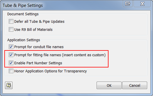
Tube and Pipe Setting Enhancements (not available in Inventor LT)
You can now customize file names for fittings and populate part numbers into your parts list within the drawing environment. Previously, you could only change the name of your conduit items, but now you can update fittings as well.
Updates to dialog box options within the Tube and Pipe environment:
Prompt for fitting file names (insert content as custom): By selecting this option, you are able to customize the name of your fittings within the Conduit File Names dialog box.
Enable Part Number Settings: Allows you to populate a part number into the parts list within the drawing environment. The part number is updated within the part file and then populates the parts list. This option also makes available the Part Number Settings options in the Conduit File Names dialog box.
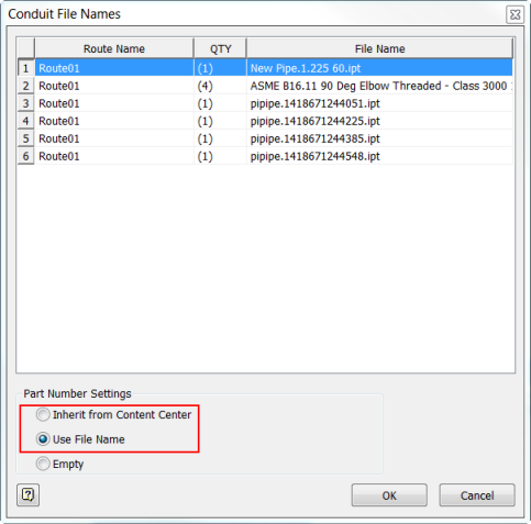
Part Number Settings: The Part Number Settings field is made available by selecting the Enable Part Number Settings check box in the Tube and Pipe Settings dialog box. New options within this dialog box are:
- Inherit from Content Center: Uses the name provided by the Content Center Library as your file name.
- Use File Name: Allows you to customize file names, later allowing you the option to populate the information to the parts list within the drawing environment.
- Empty: Available in Inventor 2014. If selected, the File name remains empty.