In this task you assign the properties necessary to run a compression molding analysis
- Rotate the model so you can select the blue cube (indicated as 1 in the image).
The blue cube represents the polymer charge which should be a realistic representation of the actual charge geometry. More information about the Initial charge can be found on the Compression Surfaces page in the help.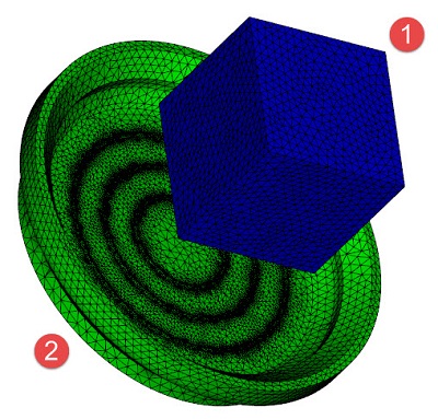
- Click
 ().
().
- Select
New drop-down list and select
Initial charge (3D) and click
OK twice.
Note: Here is where the fiber orientation in the initial charge maybe edited at any time.
- Select the green part (indicated as 2 in the image above).
- Click
(Assign ).
- Select
New drop-down list and select
Compression element (3D) and click
OK twice.
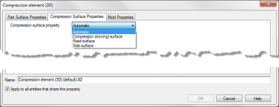
The compression element (3D) property dialog has a parameter called Compression surface property which the software uses to identify where the compression will occur. The default value is Automatic. You can check this by reviewing the compression surface property result. The automatic setting works for most parts. For more information about the Compression element (3D) options read Compression Surfaces in the help.
Click the Next topic link below to move on to the next task of the tutorial.