Control the display of parts and simulation results by clicking light bulb icons in the Browser, on the left side of the Simulation Utility window.
In the Browser, Results appear after solving a simulation. Click off the light bulbs ( ) to turn off the Geometry, Build plate or Outline display, and turn on (
 ) one of the Results, such as Displacement, Structure type, Temperature, or a Stress type.

For any of the Geometry or Results items, you can right-click for access to Render Properties and other options. Parts and support structures have the following options on the right-click menu:
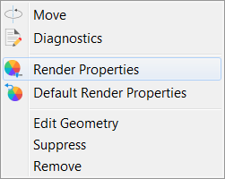
- Move opens the Move dialog, where you can translate and rotate the selected geometry. For more information, see To Move Parts.
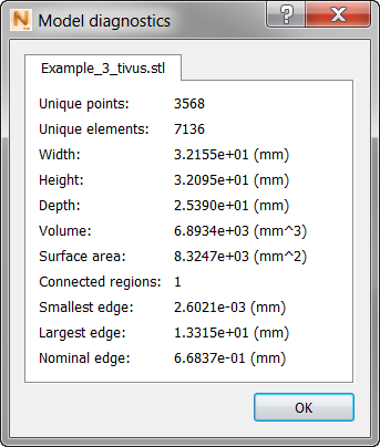
- Diagnostics displays a range of physical data about the model, as in this example:
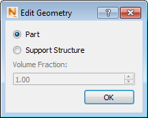
- Edit Geometry opens the Edit Geometry dialog, where you can change the geometry to a Part or Support Structure, and for a Support Structure, you can change the Volume Fraction. Refer to
How to homogenize supports for instructions on how to determine the volume fraction of a support structure.
- Suppress makes the selected geometry disappear from the display, and from being meshed or solved. The geometry can be restored to active use by means of the light bulb.
- Remove deletes the selected geometry from the project.
Structure type results
The Structure Type display color codes the results into six different element types, as follows:
0 – Build Plate
1 – Powder
2 – Part
3 – Homogenized Part
4 – Support Structure
5 – Failed Support Structure
If you open a project file (.tivus) generated with Simulation Utility 2018.1 or earlier, the structure type displays just four element types, as follows:
0 – Build Plate
1 – Part
2 – Support Structure
3 – Failed Support Structure
But if you rerun the simulation, you will see the full six structure types.
Temperature results
Several temperature result types can be displayed, depending on the PRM type and operating conditions:
- Temperature - thermal results written during the mechanical response simulation. These correspond to the time after the powder layer has been deposited and the recoater has already swept the new layer across, right before the next layer is rastered.
- Temperature (trapped powder) - thermal results of the thermal simulation which displays the powder elements in addition to the parts and supports. These only exist if Conduction to loose powder has been selected on the Operating Conditions panel. The time step is the same as the normal temperature results, right before each new layer is rastered.
- Interlayer temperature - this result type is imported whenever a PRM file containing Lack of Fusion and Hot spot information is used for a thermal or thermo-mechanical simulation. This is a global, single increment result, which shows the modeled temperature between each layer, right before the subsequent layer is rastered.
- Lack of fusion volume % below # C - this result type is imported whenever a PRM file containing Lack of Fusion and Hot spot information is used for a thermal or thermo-mechanical simulation. This is a global, single increment result, which shows the possible percentage of each element which falls below the specified temperature #.
- Hot spot volume % above # C - this result type is imported whenever a PRM file containing Lack of Fusion and Hot spot information is used for a thermal or thermo-mechanical simulation. This is a global, single increment result, which shows the possible percentage of each element that exceeds the specified temperature #.
Stress and strain results
These results are displayed for a mechanical analysis, and the specific types displayed depend on which strain and stress outputs are chosen to be recorded, and whether Structural Plasticity is set to On or Off. These controls are all located in the Solver Settings dialog, Results tab.
Recoater results
There are two recoater type results written from each thermo-mechanical simulation: Recoater Clearance % and Recoater status.
- Recoater Clearance % - displays the Recoater Clearance value of each element at each time step. This can be useful to determine exactly what location of the geometry recoater interference may occur.
- Recoater Status - displays a binary value of Recoater status for a quick visual check of whether recoater interference has occurred at each time step:
- 0 = No recoater interference
- 1 = Recoater tolerance has been exceeded during the current timestep
Named Views
These are convenient for seeing the part from different sides. To add custom views to the list, use the View Cube or Navigation Bar to set up the view, and then select Save View from the available menu. For more information about the View Cube and Navigation Bar, see Canvas and Navigation Panels.