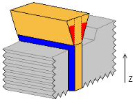
This page enables you to define the extension of the electrode that attaches the burn region to the base.
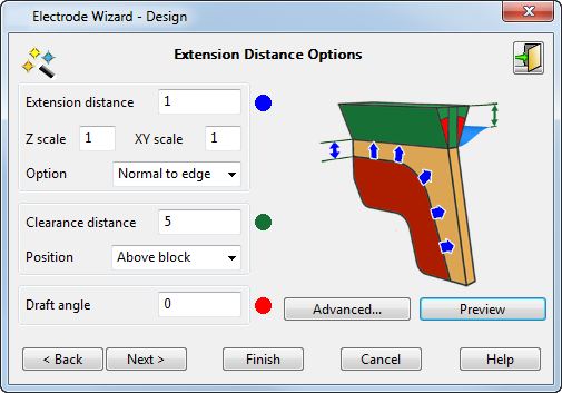
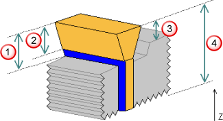
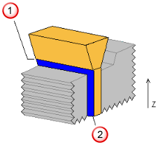
The diagram on the dialog shows where the three values refer to using the blue, red, and green colour codes.
To define the extension distance:
- Extension Distance — Enter the extension of the burn region of the electrode.
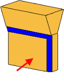
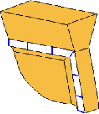
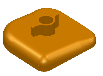
This example shows an electrode on its own, with the burn region marked with the arrow:
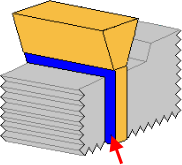
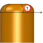
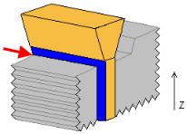
This is the electrode in a solid, with the Extension Distance marked with the arrow:
- Z scale — Enter the value you want to scale the extension by in the Z direction.
- XY scale — Enter the value you want to scale the extension by in both the X and Y directions.
If you want the extension in the Z direction to be a different length from that in the X and Y directions, use the Z scale and the XY scale boxes. However, the resulting extension is still tangent continuous with the underlying faces of the solid. Therefore the distances extended may not equal the distance multiplied by the scale factor.
Normally, you do not enter two scale values. One of the scale values remains 1 to match the length of the extension distance. If the other value is 1, then the extensions in the Z and XY directions are the same. If it is not 1, the extensions in the Z and XY directions are different.
- Option — Select how the burn region is extended.
You may find that an option does not work for a particular electrode. If you are unsure which option to use, try one and click the Preview button. If you are not happy with the results, then try another option.
Grow to Box — This option uses an expanded bounding-box of the burn region as a target to limit the extension. The surfaces are generally extended further than the extension distance until they intersect with this box. This produces a square, planar side to open-ended ribs.
The normal extension methods may not give the desired result because the angle on the edge of the rib produces an angled face on the electrode in the clearance region where the shape is not critical.
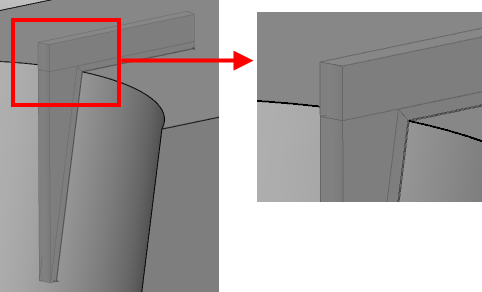
The Grow to Box solution gives a neater electrode.
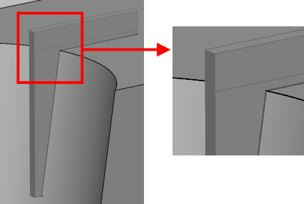
The greater the curvature of the edge of the rib, the greater the benefit of using Grow to Box.
Normal to Edge — The extension is perpendicular to the edge of the burn region.
 Burn region
 Extension
Surface Internals — The extension is along the direction of the laterals/longitudinals on the underlying surface of the burn region.
Align Vertically — The extension is aligned vertically along the Z axis.
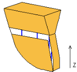
The internal curves of the extension are aligned with the Z axis, but the extension itself is still tangent continuous to the burn region. For this reason, this option is not suitable for extending faces that lie flat in the XY plane.
Split surface — The extension is along the surface normal of the underlying surface. Select this option and enter an Angle. The default angle for the split surface is 90
 .
.
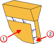
This option is most suitable for convex upstand regions. Without this option, you get a razor edge. In the diagram below, you can see an example of such a region. The arrow shows the direction of the extension.
Split surface option:
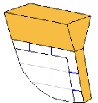
Other options:
 Burn region
This option is also suitable for regions that have fillets at their edges.
- Clearance Distance — This is the distance of the electrode base from the selected
Position option, measured along the Z axis. The base is the part of the blank at the top of the electrode.
 Above burn region
Above extension
Above burn region
Above extension
 Above block
 Above minimum Z distance
You can enter a negative value for the clearance distance. When the base is created, Electrode automatically trims it so that it does not collide with the solid. If the negative value is low enough, you can create an electrode whose base matches the top of the solid. This is known as an offset base electrode.
- Position — If you change the
Position options, the graphic in the wizard changes to show where the base position is calculated.
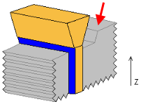
Above Block — This is the highest point of the solid from the XY plane, marked with the red arrow:
Above Extension — This is the highest point of the extension of the burn region from the XY plane.
 Above Extension
Extension Distance
Above Extension
Extension Distance
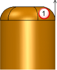
Above Burn Region — This is the highest point of the burn region from the XY plane, marked with the red arrow:
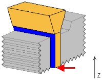
Above Z min — This is the minimum Z value of the selected burn region, marked with the red arrow:
For this option, you cannot use negative values for the clearance distance. If the clearance distance is less than the height of the burn region, an offset base style electrode is created.
- Draft Angle — This is the angle on the extension of the electrode, excluding the part which extends from the burn region. A draft angle may be required to strengthen the electrode if it is designed for a narrow cavity. It is measured from the Z axis. The draft angles are marked in red on the diagram:
- Preview — When you click this button, the extension and clearance surfaces produced by the wizard are collision-checked against the part. The user is warned of any collision.
The electrode is displayed in the model window using the values from the dialog. Change the values if necessary and click Preview again.
Advanced — This enables you to define different directions for particular segments of the electrode extension, using the Advanced Extension options.
 Exit — Click this button to exit the wizard. The electrode is created as a solid and remains selected. You can modify the solid and enter the wizard again. This will register the solid as an electrode. See
Registering a solid as an electrode for further details.
Exit — Click this button to exit the wizard. The electrode is created as a solid and remains selected. You can modify the solid and enter the wizard again. This will register the solid as an electrode. See
Registering a solid as an electrode for further details.
- Next — The extension and clearance surfaces produced by the electrode wizard are collision-checked against the part. You are warned of any collision and the Specify Electrode Blank page of the Electrode Wizard -Design is displayed.