Use this page to specify the blank of the electrode, when the product is an active solid, and the electrode is a pre-selected solid without a blank.
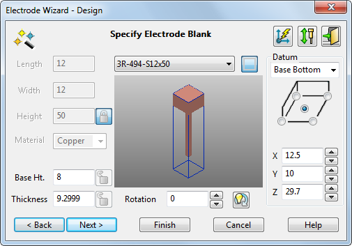
The top part of the blank forms the base of the electrode. The base is drawn in the model window using the values in the wizard. As you update the blank in the wizard, the electrode updates in the model window.
You can rotate, zoom, and pan the image of the electrode in the wizard using the mouse.
To specify the blank:
 — Select a blank from the list of available standard blanks that fit the dimensions of the electrode. You can
add your blanks to this list.
— Select a blank from the list of available standard blanks that fit the dimensions of the electrode. You can
add your blanks to this list.
The options available in this dialog depend on the blank you select from the list.
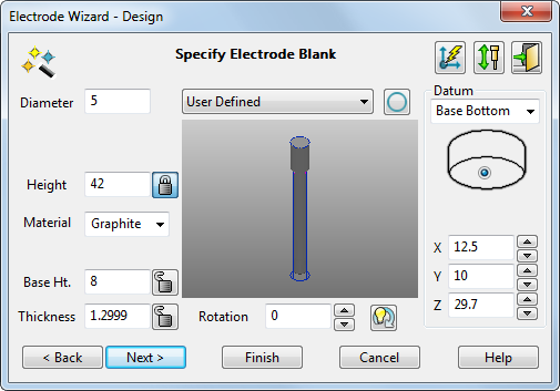
You can create a custom blank by selecting the User Defined option from the list. Additional options become available:

 Shape — If you selected a standard blank, the shape of the blank is shown by this icon. You cannot change the shape of a standard blank.
If you are creating a user-defined blank, you can toggle this button to set the shape. Ensure the rectangle
 icon is displayed to create a rectangular blank. Ensure the circle
 icon is displayed to create a circular blank.
Length — If you are using a standard rectangular blank, the length is displayed. If you are creating a user-defined rectangular blank, enter the length.
Width — If you are using a standard rectangular blank, the width is displayed. If you are creating a user-defined rectangular blank, enter the width.
Diameter — If you are using a standard circular blank, the diameter is displayed. If you are creating a user-defined circular blank, enter the diameter.
Height — If you are using a standard blank, the height is displayed. If you are creating a user-defined blank, enter the height.
Tip: Height, Thickness, and Base Ht. are related. If you change one value, another value also changes. For further details, see Tips for creating electrodes.- Material — If you are using a standard blank, the blank material type is displayed. If you are creating a user-defined blank, select the material type from copper or one of three grades of graphite.
The details of the different grades of graphite are given below.
Name
Grade
Grain size
Graphite-1
High
< 3
 m
m
Graphite-2
Medium
3-10
m
Graphite
Low
> 10
m
These grades are used by the Electrode Family page when using the recommended values for the undersizes.
The electrode is shaded using the chosen material.
Tip: You can add new materials to this list. - Base Ht. — Enter the height of the base.
- Thickness — This is the minimum Z thickness that is machined from the blank. It is the amount of waste. By setting a small Thickness, you can minimise the waste material and the amount of machining required. You should use zero thickness only if the blank has been pre-ground to the desired surface finish.
- Rotation — This rotates the blank around the Z axis by the given angle. Enter a rotation angle or use the arrow buttons to specify the angle.
Click
 to automatically rotate the electrode blank to the best position so that the minimum amount of blank material is wasted.
Tip: If you rotate the blank, you may be able to specify a smaller blank for the electrode. This can reduce the amount of material wasted and also save on machining time.
to automatically rotate the electrode blank to the best position so that the minimum amount of blank material is wasted.
Tip: If you rotate the blank, you may be able to specify a smaller blank for the electrode. This can reduce the amount of material wasted and also save on machining time. - Datum — This gives the position of the electrode in the model and is used for machining purposes. For each of the options, you click radio buttons to choose where the datum is positioned.
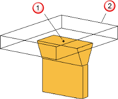
Use the list to select the face of the electrode where the datum lies. The faces of the electrode are: the Base Top, the Base Bottom, and the Electrode Bottom. If you change the face, the image below the list changes.
For the Base Bottom option, the image looks like:

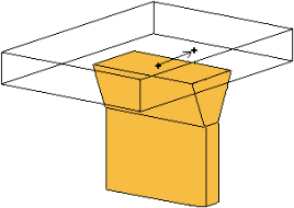
For the Base Top option, it looks like:

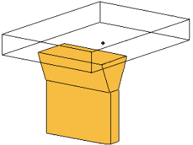
For the Electrode Bottom option, it looks like:

When a circular blank is selected, the image looks like:

For circular blanks, the datum can be positioned at the centre of each face.
- X,
Y, and
Z — These are the coordinates of the datum relative to the current workspace. If you change these values, the base of the electrode moves relative to the datum. Suppose you have the following.
 Datum in the middle of the bottom face
 Electrode base
Move the datum as shown below:
The base moves too.
The Z coordinate is available only if you select Base Top or Base Bottom. If you change the Z value, the height of the base changes.
Note: For EDM setup, the actual position values are rounded to the nearest 0.1mm/0.01 inch/10 thousandths.  Vector Burn — Click this button to display the
Vector Burn
dialog.
Vector Burn — Click this button to display the
Vector Burn
dialog.
 — Click this button to raise the
Electrode Simulation dialog.
— Click this button to raise the
Electrode Simulation dialog.
- Next
— Adds alignment notches to the base and displays the
Specify Electrode Holderpage of the Electrode wizard.
Alternatively click
 to exit the wizard. The electrode and base are created as separate solids and remain selected. You can modify the solids, add them together, and enter the wizard again. This
registers the solids as an electrode.
to exit the wizard. The electrode and base are created as separate solids and remain selected. You can modify the solids, add them together, and enter the wizard again. This
registers the solids as an electrode.