In this task, you will interpret deflection results to determine how much the part has warped.
 Download the files for this tutorial from
Autodesk Knowledge Network-New User Quick Start tutorial.
Download the files for this tutorial from
Autodesk Knowledge Network-New User Quick Start tutorial.
- To investigate the analyzed study, import MouseCover_warpage.sdy from where you saved the tutorial files.
-
Display only the MouseCover Tetras layer.
-
Rotate, the model to -30 15 35.
-
Select the Deflection, all effects:Deflection result in the study tasks list.
Variations from cavity to cavity for fill time, pressure, and temperatures will cause differences between parts. For this tutorial we will assume that all parts are the same regardless of the cavity they were molded in.
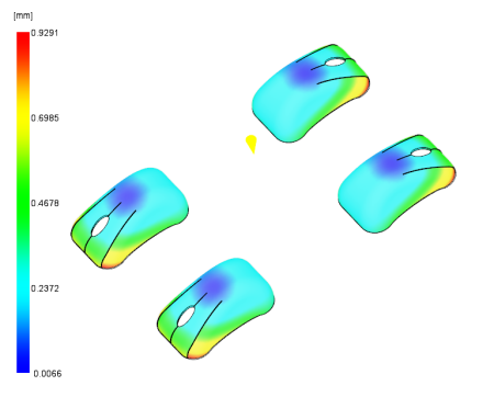
Figure 1: Deflection, all effects:Deflection
-
Zoom up on one of the parts.
The red outside edge of the part indicates nearly double the deflection of the inner two green edged tabs. To more clearly view the warpage we are going to scale the deflection by a factor of 5.
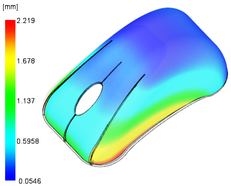
Figure 2: Deflection, all effects
-
Click
 ().
().
- Click the Deflection tab.
- Enter 5 for the Scale Factor Value and only display the X and Y directions.
- Click OK.
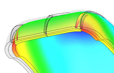
Figure 3: Deflection, all effects:Deflection - scale factor of 5
This result seems to indicate that the deflection would cause the four separate sections to overlap and extend through each other. This is not possible. The result shows the magnitude of the unconstrained deflection of the part. In reality, these four sections would physically interact causing additional distortion.
In the next task we will investigate the possible reasons for this deflection.