An overview of how to use Autodesk Simulation Utility for Netfabb and where to get more information.
How to set up a part-scale powder bed fusion simulation
- On the Simulation menu, review and adjust
Simulation settings as necessary.

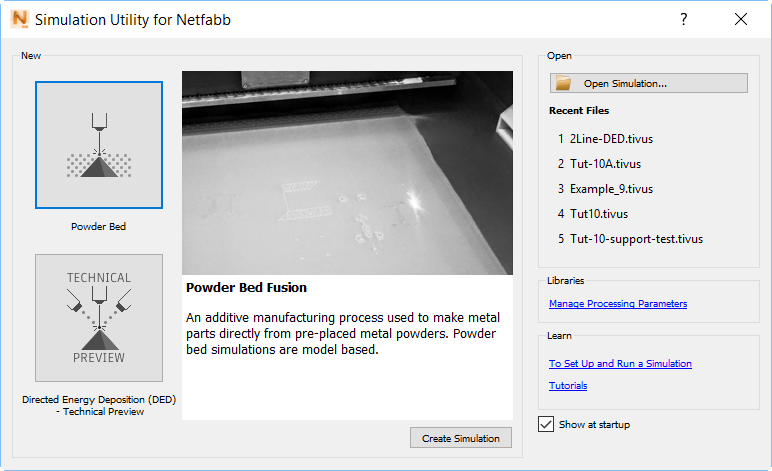
- Create a new simulation project and select
Powder Bed Fusion.
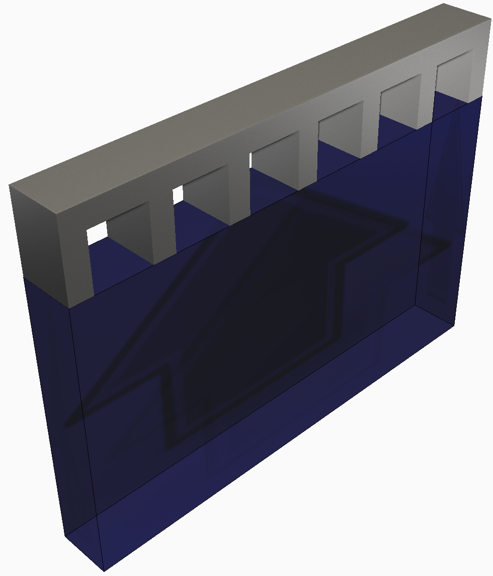
- Import one or more 3D geometric files for which to simulate the additive manufacturing process. One or more additional geometry files may be imported to model support structures.
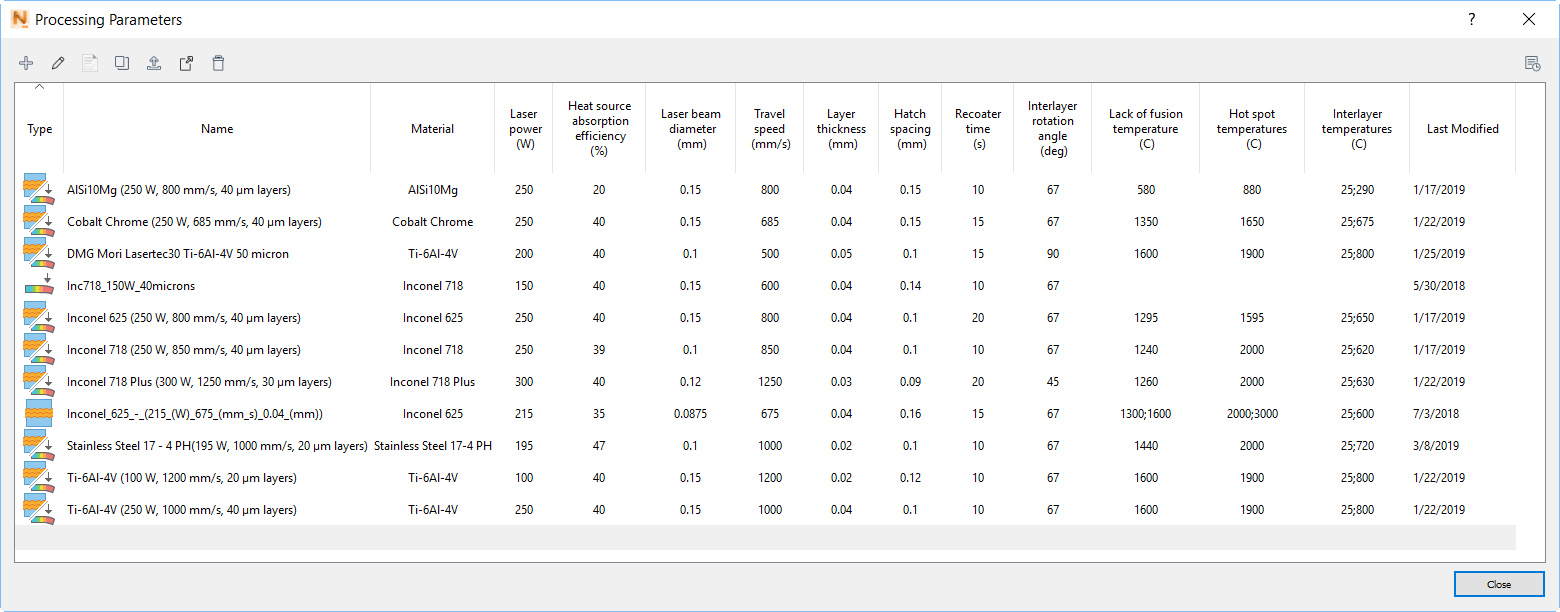
- In the
process parameter (PRM) file library, identify a PRM file that matches the processing parameters and material of the part to simulated, or create a new custom PRM file if none currently exists.
Note: A license of Local Simulation is required to generate new PRM files.
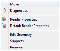
- If necessary,
adjust the orientation of the part by right clicking on the part in the Browser and selecting
Move.
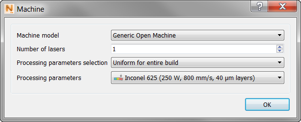
- In the
Machine dialog specify the PRM file for the processing parameters and material of the component.
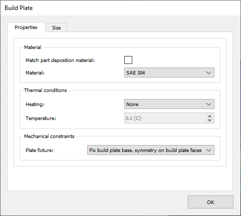
- Use the
Build Plate panel to specify the build plate material, size, build plate heating, and mechanical constraints.
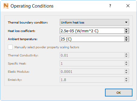
- In the
Operating Conditions dialog, choose the ambient temperature and thermal boundary conditions during processing.
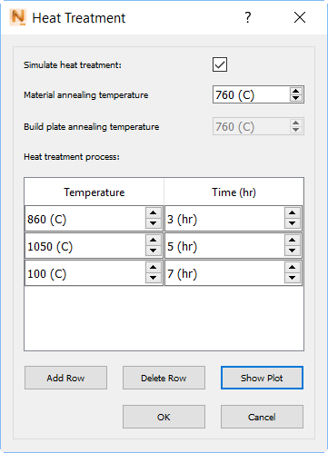
- Use the
Heat Treatment panel to detail the time-temperature values of a stress relief heat treatment cycle, if one is used.
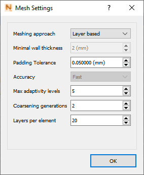
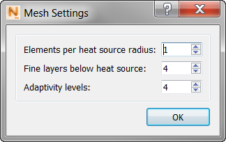
- Select
mesh settings appropriate for the size and complexity of the component.
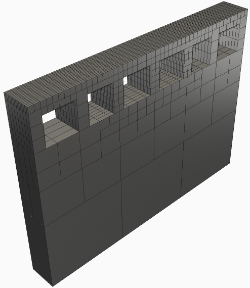
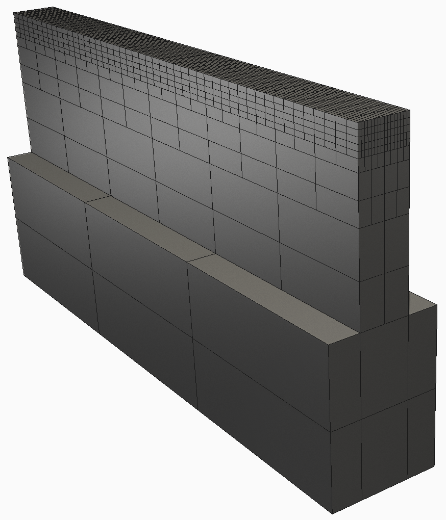
- Generate a
Mesh Preview to ensure adequate voxel representation of the source geometry and to check for flaws in the mesh that could affect simulation results.
- Solve the simulation on the local computer.

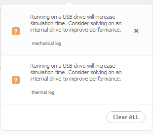
- Reference any notifications in the top right of the screen as they appear or
review the log files for errors or warnings.
- Examine model results.
How to set up a directed energy deposition simulation
Note: Simulation Utility LT cannot run directed energy deposition (DED) simulations. These require the full
Simulation Utility, installed with
NetfabbLocal Simulation.
- On the Simulation menu, review and adjust
Simulation Utility settings to suit your project if necessary.
- Create a new simulation project and select Directed Energy Deposition.
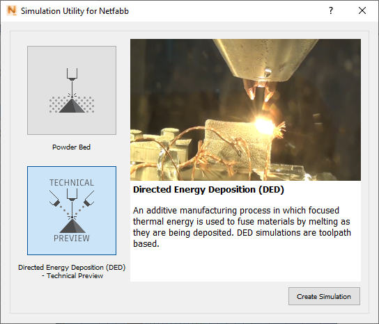
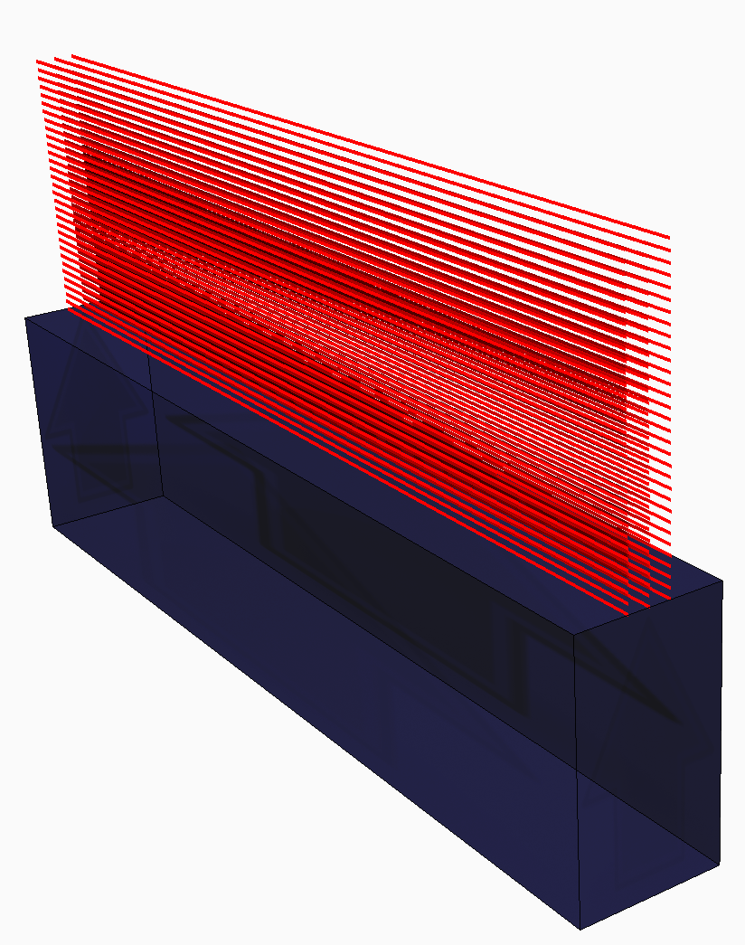
- Import
a laser vector (LSR) file. An LSR file specifies the power, speed, laser spot size, beginning and end points, and timing of the laser vectors to build a DED component.
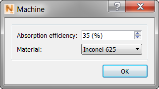
- Specify the material and absorption efficiency on the
Machine panel. Laser based DED systems absorption efficiencies are generally in the range of 30-40%. Electron beam systems typically have much higher absorption efficiencies, between 88-98%
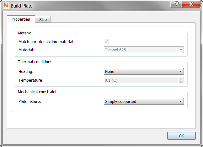
- In the
Build Plate dialog, specify the size, build plate heating, and mechanical constraints.
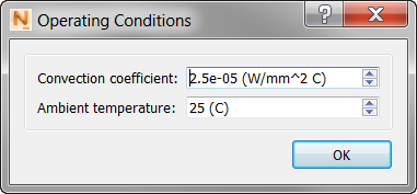
- In the
Operating Conditions dialog, choose the ambient temperature and global convection coefficient during processing.
- Select
mesh settings appropriate for the size and complexity of the component.
- Generate a mesh preview to ensure adequate voxel representation of the source geometry and to check for flaws in the mesh that could affect simulation results.
- Solve the simulation.
- Reference any notifications in the top right of the screen as they appear or
review the log files for errors or warnings.
- Examine model results.
See the Tutorials in the Help for videos and step-by-step walkthroughs of simulation solutions, using sample files that you can download from an Autodesk website.