The Geometry (All) panel provides a subset of modeling tools from the Edit Geometry rollout and adds Cap Poly for creating a polygon from a vertex or edge selection and the Quadrify tools for converting polygons to quadrilaterals.
Interface
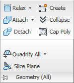
Geometry (All) panel on maximized ribbon, with expansion
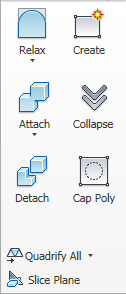
Geometry (All) panel on minimized ribbon
-
 Relax
Relax
- Applies the Relax function to the current selection, using the current Relax settings (see following). Relax normalizes mesh spacing by moving each vertex toward the average location of its neighbors. It works the same way as the Relax modifier.
At the object level, Relax applies to the entire object. At sub-object levels, Relax applies only to the current selection.
Note: To open the Relax Settings dialog, use the drop-down menu or Shift+click the Relax button. - Relax Settings (on Relax drop-down)
- Opens the Relax caddy, which lets you specify how the Relax function is applied.
-
 Create
- Lets you create new geometry. How this button behaves depends on which level is active:
- Object, Polygon, and Element levels Add polygons in the active viewport by clicking existing or new vertices.
- Vertex level Add vertices to a single selected poly object by clicking anywhere in the active viewport.
- Edge and Border levels Add edges between pairs of non-adjacent vertices on the same polygon.
-
 Attach
- Lets you attach other objects in the scene to the selected poly object. After activating Attach, click an object to attach to the selected object. Attach remains active, so you can continue clicking objects to attach them. To exit, right-click in the active viewport or click the Attach button again.
You can attach any type of object, including splines, patch objects, and NURBS surfaces. Attaching a non-mesh object converts it to editable-poly format.
When you attach an object, the materials of the two objects are combined in the following way:
- If the object being attached does not have a material assigned, it inherits the material of the object it is being attached to.
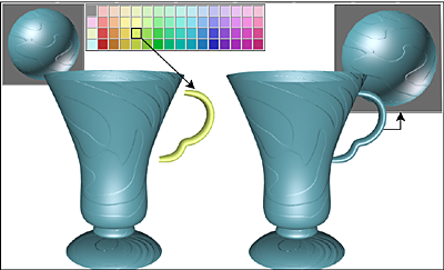
Handle inherits material from the cup it is being attached to.
- Likewise, if the object you're attaching to doesn't have a material, it inherits the material of the object being attached.
- If both objects have materials, the resulting new material is a multi/sub-object material that includes the input materials. A dialog appears offering three methods of combining the objects' materials and material IDs. For more information, see Attach Options Dialog.
Attach remains active in all sub-object levels, but always applies to objects.
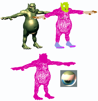
Upper left: Shaded view of model
Upper right: Wireframe view of model
Lower left: Model with objects attached
Lower right: Subsequent multi/sub-object material
Note: To attach objects from a list, use the drop-down menu or Shift+click the Attach button. - If the object being attached does not have a material assigned, it inherits the material of the object it is being attached to.
-
 Attach from List (on Attach drop-down)
- Use to attach objects from a text-based list. Opens the Attach List dialog; highlight the objects to attach, then click Attach.
-
 Collapse (Sub-object levels only)
- Collapses groups of contiguous selected sub-objects by welding their vertices to a vertex at the selection center.
Using collapse on a vertex selection
Using collapse on a polygon selection
-
 Detach (Sub-object levels only)
-
Separates the selected sub–objects and associated polygons as a new object or element(s).
When you click Detach, the software prompts you for the options specified on the Detach dialog. If the object is in Edit Poly (modifier) format, you can detach using the current settings without opening the dialog by Shift+clicking the Detach button.
-
 Cap Poly
-
Creates a single polygon from a vertex or edge selection and selects the polygon. Available at the Vertex, Edge, and Border sub-object levels only.
Select vertices or edges and then click Cap Poly.
Using Cap Poly with a vertex selection
Using Cap Poly with an edge selection
Using Cap Poly with a border selection
Tip: For best results when capping an entire border, use Cap Poly at the Border sub-object level. To see why, please read the following section.When capping an edge selection, the software uses the edge vertices to determine the feasibility of creating a polygon. When using Cap Poly at the Vertex or Edge level, the software requires a non-overlapping counter-clockwise sequence of selected sub-objects. Consider the example shown in the following illustration, in which the goal is to cap all border edges or vertices:
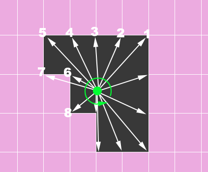
The software first determines the geometric center of the selected sub-objects (the small green disc), and then shoots out “rays” in counter-clockwise order from that location to find the locations of vertices from which to form a polygon. In this case, it finds vertex 6 before it finds vertex 7, but vertex 7 actually precedes vertex 6 when going around the border in counter-clockwise order. As a result, Cap Poly cannot form the polygon because the vertices it finds are in the wrong order.
In such cases, apply Cap Poly at the Border sub-object level.
- Quadrify ...
-
A set of tools for converting triangles to quadrilaterals. Click the visible tool to apply it, or choose another tool from the drop-down list.
- Quadrify All Removes edges from the entire object to convert triangles to four-sided polygons.
- Quadrify Selection Removes edges from the current sub-object selection to convert triangles to four-sided polygons.
- Select Edges from All Selects edges that would be removed in a Quadrify All operation.
To see the selection, go to the Edge sub-object level.
- Select Edges from Selection Selects edges that would be removed in a Quadrify All operation.
To see the selection, go to the Edge sub-object level.
Tip: For best results, the geometry to quadrify should be fairly uniform.Tip: Another way to convert a mesh to quads is with the Quadify Mesh modifier. - Slice Plane (sub-object levels only)
-
Creates a gizmo for a slice plane that you can position and rotate to specify where to slice. Also enables the Slice and Reset Plane buttons; click Slice to create new edges where the plane intersects the geometry.
If you use Slice Plane from the ribbon, the Slice, Split, and Reset Plane controls are available on the Slice Mode contextual panel.
If snapping is off, you see a preview of the slice as you transform the slice plane. To perform the slice, click the Slice button.
Note: At the Polygon or Element sub-object level, Slice Plane affects only selected polygons. To slice the entire object, use Slice Plane at any other sub-object level, or at the object level.