Use this procedure to define an object as a layout curve. The spacing between anchor nodes determines the spacing between objects that you attach to the layout curve, even if you change the geometry of the layout curve.
The following spacing options are available:
- Manual: You specify the position of each node along the layout curve.
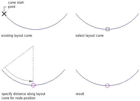
Manually placing a node on a layout curve
- Repeat: You specify equidistant spacing between nodes along the layout curve. The number of anchor nodes is determined by the length of the layout curve. As the length of the curve changes, nodes are added or subtracted accordingly. The spacing of the nodes remains fixed.
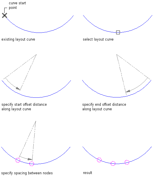
Placing nodes at repeat spacing on a layout curve
- Space Evenly: You specify the number of nodes along the curve. The space between nodes is determined by the length of the layout curve. As the length of the curve changes, the spacing between nodes is lengthened or shortened accordingly. The number of nodes remains fixed.
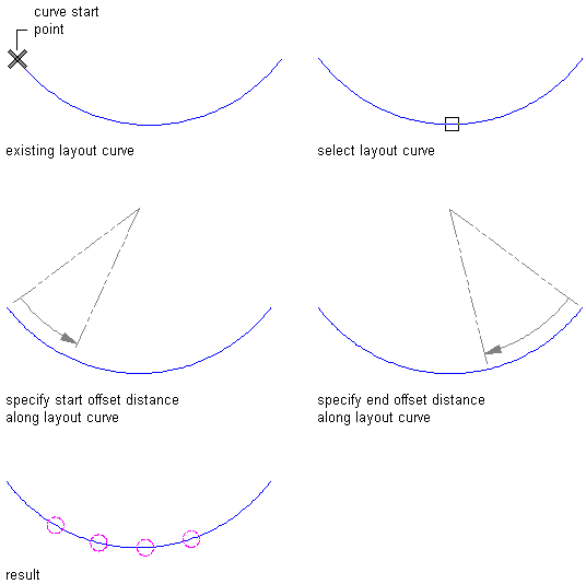
Placing nodes at even spacing on a layout curve
- Open the tool palette that contains the layout curve tool you want to use, and select the tool. Tip: You may have to scroll to display the desired tool. After selecting it, you can move or hide the Properties palette to expose more of the drawing area.
If there are no layout curve tools available on tool palettes in the workspace, you can use the Content Browser to access the Stock Tool catalog, which contains a layout curve tool under Parametric Layout and Anchoring Tools. You can add this tool to any tool palette.
- Select the object to define as a layout curve.
- Place nodes along the layout curve:
If you want to… Then… Place nodes at locations that you specify press Enter. Enter the number of nodes, and specify the locations of nodes by selecting them or by entering distances from the start point of the curve. Repeat nodes at fixed intervals along the curve enter r (Repeat). Specify the start and end offsets of the first and last nodes, and specify the spacing between nodes. Space a fixed number of nodes along the curve enter s (Space evenly). Specify the start and end offsets of the first and last nodes, and specify the number of nodes.