Use this procedure to set up standard styles and display settings for a project.
To set up standard styles and display settings, you define one or more project standards drawings that contain the standards for styles and display settings. These drawings can be DWG, DWT, or DWS files and are added in the configuration dialog box.
Standard files are marked by icons next to their name in the configuration setup.
| Icon | Description |
|---|---|
|
|
Standards drawing (DWG) |
|
|
Standards template (DWT) |
|
|
AutoCAD Standards file (DWS) |
|
|
Missing standards file |
Synchronization Order
If you have multiple standards drawings associated with a specific style type, then during synchronization the occurrence of the style in the first standards drawing is used as the style with which the style in the project drawing is synchronized. Further drawings containing the same standard style are ignored.
Order of standards drawings
- Click

 Open Project. Note: To access the standards configuration of the current project only, click.
- Select the project for which you want to configure standards, right-click, and click Project Properties.
- Expand Advanced and click Project Standards
 .
. 
- To add a new standards drawing for styles, click
 .
. - In the Select Standards Drawing dialog box, select a DWG, DWT, or DWS file that contains standard styles, and click Open.
If you do not yet have standards drawings, create a new project standards drawing.
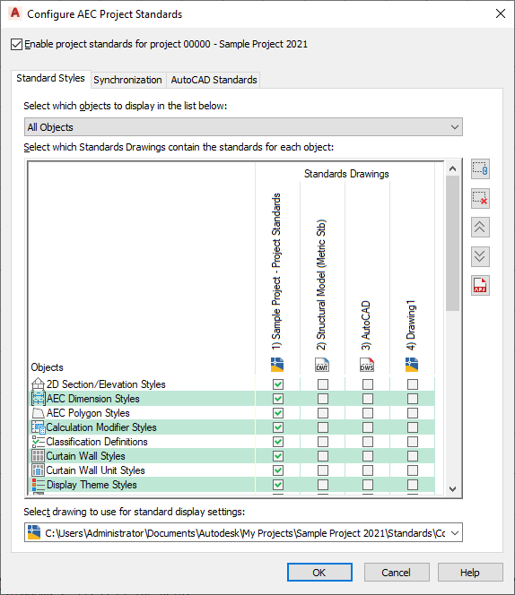
The new styles drawing is appended to the Standards Drawings list. The order of the columns, from left to right, defines the search order and precedence during synchronization. To change the order of the drawings, select the drawing name in the column header, and click
 to move the drawing up in the drawing order, and click
  to move the drawing down in the drawing order.
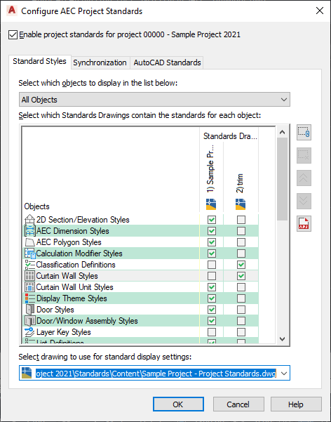
 After you have added styles drawings to the project standards setup, you need to define for which style types each drawing should be the standard. To do this, you associate each style type with a standards drawing. The style types are listed under Objects in the Standard Styles tab. You can find all style types from Style Manager here.
- To display only style types of one style category, select the category under Select which objects to display in the list below. If you want to see all style categories, select All Objects.
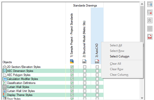
- To define that a specific style type should be controlled by a specific standards drawing, click the style type’s check box in the appropriate drawing column. Tip: If you want to select one drawing for all style types, right-click in the header, and click Select Column.
If a style type has not been associated with a standards drawing, these styles are not controlled by the standards. For example, if the standards drawing “Standard Styles 1.dwg” has not been associated with the Wall Styles type, then even if wall styles from this standards drawing exist in a project drawing, they will be interpreted as “not standardized” by the synchronization.
If you select multiple standards drawings for one style type, then during synchronization, each drawing is searched for that style type in the order of the drawings. This means that you can distribute standard styles for a style type among different drawings. For example, you could store your concrete wall styles in the standards drawing “Wall Styles - Concrete (Imperial)”, and your brick wall styles in the drawing “Wall Styles - Brick (Imperial)”.
Note: If two standards drawings contain a style of the same name and type, the style in the first standards drawing will be used for synchronization. Further instances of that style will be ignored. The order of standards drawings is determined by their position from left to right in the table. To re-order the drawings, use the Up and Down buttons. - To remove a standard styles drawing from the project, click on its name in the Standards Drawings list, and click
 .
. Removing a standards drawing from the list only removes the reference of this drawing to the project. The drawing is not deleted from the file system.
Next, you need to define a standards drawings for the display settings in the project. You can assign only one standards drawing for display settings. The standard display settings drawing can be one already assigned as a styles standards drawing.
- Under Select drawing to use for standard display settings, select a file. If necessary, select Browse to browse for a file. Note: If you are using a display standards drawing that is different from the styles standards drawing, or if you have multiple styles standards drawings, you need to make sure that the styles standard drawings are in synch with the display standards drawing.
- Click the Synchronization tab.
If you have added a standards drawing to the project, and the drawing is located in the project folder, the drawing will automatically have initial version information added to all styles and display settings. If the new standards drawing is located outside the project folder, and has not yet been versioned, you need to version it.
- If necessary, enter a universal comment to all versioned styles and display settings.
For instance, you might want to add a comment to indicate what has changed in the style as of this version.
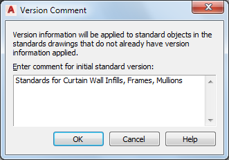
- Click OK. Note: If some of the standards drawings have been set to read-only, they cannot be automatically versioned. In this case, they need to be versioned manually by a user with read-write access.