- Open the tool palette that contains the door/window assembly tool you want to use, and select it. Note: Alternatively, you can click


 .
. 
- On the Properties palette, expand Basic
 General, and select a style.
 - Under Bound Spaces, specify if this door and window assembly can be used as a bounding object for associative spaces.
You can select three options here:
- Yes: this door and window assembly can be used as bounding object for associative spaces.
- No: this door and window assembly cannot be used as bounding object for associative spaces.
- By style: this door and window assembly will use the bounding settings from the door and window assembly style.
- Expand Dimensions and modify the dimensions of the door/window assembly.
If you want to specify… Then… the length of the door/window assembly enter a value for Length. the height of the door/window assembly enter a value for Height. the rise of the door/window assembly enter a value for Rise. start and end miters enter miter values for Start miter angle and End miter angle. - Expand Location and modify the location properties of the door/window assembly.
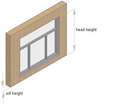
If you want to specify… Then… the position of the door/window assembly select Unconstrained or Offset/Centered for Position along the wall. Note: If you selected Offset/Centered, enter a value for the Automatic offset.the vertical alignment of the door/window assembly select Head or Sill for Vertical Alignment. the head height of the door/window assembly enter a value for Head height. the sill height of the door/window assembly enter a values for Sill height. the rotation reference angle of the door/window assembly enter a value for Rotation. Vertical alignment controls how you place the door/window assembly in the wall and how the door/window assembly responds to modifications in height. The Sill height and Head height options allow you to determine the working point on the door/window assembly. You can place the working point at the sill or at the head. The vertical alignment value determines the location of the working point vertically in the wall.
Modifications to the door/window assembly height respect the working point. For example, if you specify the working point of the window as sill, the vertical alignment as 0'', and the door/window assembly height as 7'–0'', the height in the wall where the top of the door/window assembly is placed is 7–0''. If you modify the height of the window to 6'–8'', the window sill remains at 0'', and the top of the door/window assembly becomes 6–8''. The sill working point is maintained.
If you specify the working point as the door/window assembly head, the Vertical Alignment value as 7'–0'', and the door/window assembly height as 7'–0'', the height in the wall where the top of the door/window assembly is placed is 7–0''. If you modify the height of this door/window assembly to 6'–8'', the door/window assembly head remains at 7'–0'' and the window sill becomes 4''. The head working point is maintained.
 Tip: You can move or hide the Properties palette to expose more of the drawing area.
 - In the drawing area, select a wall, or press Enter and then specify the insertion point of the door/window assembly.
- Continue adding door/window assemblies, and press Enter.