Use this procedure to place a callout that creates a four-way exterior elevation.
Note: The 2D section/elevation style and the display set for the model space views containing the elevations are set in the elevation mark tool.
- On the Quick Access toolbar, click .

- Click the Views tab.
- Select the view drawing in which you want to place an elevation callout, right-click, and click Open.
- On the Tool Palettes, click
 (Properties), and click Document.
 - Click the Callouts palette.
- Select a four-way exterior elevation callout tool.
Alternatively, you can click
 .
. 
- Specify the first corner of the elevation region.
- Specify the opposite corner of the elevation region.
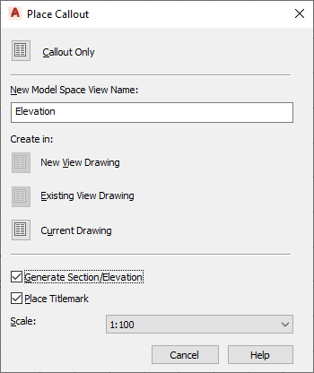
- Under New Model Space View Name, enter a name for the model space view containing the first elevation.
- Verify that Generate Section/Elevation is selected.
- If you want to add a title mark to the new model space views, select Place Titlemark.
- Select the scale for the model space view.
- Select where to place the elevation:
If you want to… Then… place the elevation in the view drawing in which you placed the callout in click Current Drawing. place the elevation in an existing elevation view drawing click Existing View Drawing. place the elevation in a new elevation drawing click New View Drawing. - Specify the height of the elevations.
- Specify the insertion point of the elevations. Note: If you chose to place the elevations in a different drawing, you still select the insertion point in the current drawing. The elevations however, will be inserted in the drawing you specified.
- Specify the distance between the elevations and their orientation.
Once the model space views have been placed, the field placeholders in the callout change to a question mark. To resolve them, the model space views need to be placed onto sheets.