Insert wires individually, insert multiple wires, and interconnect components. Wires insert with automatic connection and wire crossing gaps or loops.
Insert Wires
-
Click
 . Find
Click the Insert Wires drop-down to access the Insert 22.5, 45, or 67.5 Degree Wire tools.
- Select the starting point of the wire. You can start a wire segment in empty space, from an existing wire segment, or from an existing component. If you start from a component, the wire segment is started at the nearest wire connection attribute to your pick point on that symbol.
During wire insertion, the current wire type displays at the command prompt.
- T = override the current wire type. Select a new wire type from the Set/Edit Wire Type dialog box. The new wire type becomes the current wire type and the command continues with the wire insertion.
- X = show the wire connection points when the wire approaches a component.
-
TAB = temporarily disable or enable collision checking during wire insertion.
This setting is remembered only for the current session. Collision checking is on when AutoCAD Electrical toolset restarts.
- V = force a vertical direction for the wire segment.
- H = force a horizontal direction for the wire segment.
- C = insert the next wire segment at the current cursor location and continue wire insertion.
- Select the ending point of the wire. You can end the wire segment or angled segment in empty space, from an existing wire segment, or from an existing component. If it ends at a wire segment, a dot (wddot.dwg) is applied, if appropriate. If it ends at another component, the nearest wire connection attribute is found and connected to your pick point on that symbol. Note: If the distance between two horizontal wires is relatively small, the vertical wire crossing them avoids inserting loop gaps. The wire trap distance setting is used to see whether wire loop gaps are possible or not. Reduce the scale factor or increase the distance between two wires to insert gap loops.
If the wire was an angled wire, press “N” to switch to normal 90-degree wire mode. The wire picks up at the end of the angled wire segment and defaults to horizontal or vertical.
Insert Multiple Wires
-
Click . Find
- Set the horizontal and vertical spacing for the wires.
- Specify where to start the wires.
- Set the number of wires to 3, and click OK.
During wire insertion, the current wire type displays at the command prompt. The current wire type indicates the layer name in which the new wires are drawn. You can override it by typing "T" and selecting a new wire type from the Set/Edit Wire Type dialog box. The new wire type becomes the current wire type and the command continues with the wire insertion.
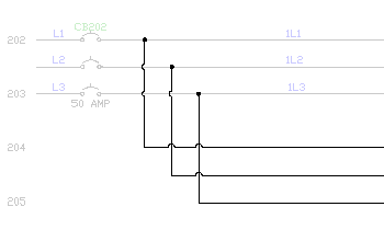
- If starting at a component or bus, select the component. Drag the cursor slowly to the right as the second and third phases latch on to their appropriate vertical wires. You can see the three wires stretch straight across the screen.
As you pull the 3-phase wire out, you can turn a corner by moving your cursor out of line with the bus. To reverse the phase sequence of the turn, press F.
- Right-click to terminate the wires. The wires and wire connection dots insert, and loops are automatically inserted at wire crossing points. Note: If the distance between two horizontal wires is relatively small, the vertical wire crossing them avoids inserting loop gaps. The wire trap distance setting is used to see whether wire loop gaps are possible or not. Reduce the scale factor or increase the distance between two wires to insert gap loops.
To tie the new 3-phase wire to an existing bus, but with reversed sequence, start the new 3-phase wire connected at the last wire on the existing bus. Move the cursor backward across the other wires until the connections are made, and then move the cursor forward again. This results in a reversed sequence connection.
Interconnect Components
-
Click . Find
- Select the first component.
- Select the second component.