Insert individual wires or insert multiple bus wiring.
Insert Wires
Inserts a line or series of lines on a defined wire layer in AutoCAD Electrical toolset. A drawing can have multiple wire layers. Wires do not have to begin or end at snap points, and can be at any angle. A wire network is one or more wire segments and optional branches that interconnect and form an electrically unbroken conductor.
You can insert single or angled (22.5, 45, or 67.5 degree) line wire segments on a wire layer (the wire layer does not have to be the current layer). AutoCAD Electrical toolset supports scooting components along angled wires.
Insert Multiple Wires
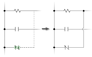
Multiple bus wiring breaks automatically and reconnects to any underlying components in its path. If it crosses existing wiring, wire-crossing gaps insert automatically based on the drawing properties. You define the number of wires.
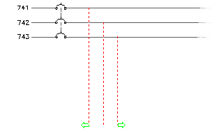
Inserts vertical or horizontal bus wiring. Bus spacing defaults to the default ladder rung spacing for horizontal bus. For a vertical bus, the spacing is the default value defined in the Ladder Defaults section in the Drawing Properties  Drawing Format dialog box.
Interconnect Components
Inserts wires between aligned connection points on a pair of selected components. Wires are added only if the wire connection points are aligned.