Create drawings, add drawings to a project, and manage the drawing settings.
Use Project Manager to create and add drawings to a project. Find
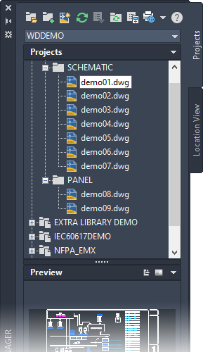
The drawing order determines the process order when project-wide functions are used. You can drag and drop within a project to reorder the drawings. You can also add folders within a project to organize drawings.
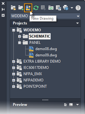
Create a Drawing
Use the New Drawing tool to create a drawing. Creating a drawing in Project Manager adds it to the active project. It is added at the end of the drawing list. Drag and drop it to change the order.
You can provide a drawing template name on the Create New Drawing dialog box. The drawing template can contain electrical drawing properties, wire layers defined (discussed later on), a reference system such as ladders or an XY Grid, and a title block.
Drawing Properties
The Drawing Properties control many of the functions in AutoCAD Electrical toolset. They include:
- Drawing values: sheet, installation, location
- Reference system: ladder, XY Grid, or XZones
- Format: component tag, wire number, cross-reference
- Style: PLC modules, wire crossing, wire connection
- Layers: component attributes and graphics, wires
If you use a drawing template when you create a drawing, the template can have the Drawing Properties predefined. If not, the drawing properties are inherited from the drawing defaults defined for the project. Click OK-Properties on the Create New Drawing dialog box to override any default drawing properties as you create a drawing.
Drawing Properties can be changed later, but you may need to run multiple commands to update the components, wire numbers, and more. So it is best to define the drawing properties before you start inserting ladders, components, modules, and wires.

Use the tabs to change to each property type.

Copy a Drawing
Use Project Manager to copy a single drawing from any open project and add it to the active project.

Add Drawings
Add existing drawings to an active project at any time. This is useful if you want to reuse drawings from a previous project. To add or create drawings in a specific folder, right-click on the folder name in Project Manager and select the drawing option.

The drawing properties can be inherited from the drawing defaults defined for the project. Use the Project-Wide Update/Retag command (talked about later), to quickly update ladder references, retag components and wire numbers, update cross-referencing, and more.
Reference Only Drawings
You may have drawings that are part of the project but you don't want them processed during project-wide functions. Or perhaps they are not even electrical drawings but they are necessary for the entire design. You can set these drawings as reference only in the drawing properties.

Tagging, cross-referencing, and reporting functions ignore reference only drawings. However, you can select to include them in project-wide plotting and title block updates.
Title Block
If you insert a .dwg as a title block on your drawings, you can link project and drawing property values to specific attributes on the title block. You need to set up the mapping between the properties and the attributes. Use the Title Block Setup command to create and define the title block mapping. The mapping can be project-specific or default for all projects. Find
If your title block is part of your drawing template, AutoCAD Electrical toolset automatically updates these attribute values when you create a drawing. Or use the Title Block Update command to update later. For example, you can renumber the sheet values across the project and update the attribute associated with that property.
Reference System
Each schematic drawing can have a reference system defined; ladders, X-Y Grid, or X Zones. The reference system is used to assign unique schematic component tags and unique wire numbers (if not using sequential tagging). The reference system is also used for cross-referencing which we cover later.
Select your reference system in Drawing Properties  Drawing Format tab Format Referencing section. Use the Setup button to define the specifics for the referencing type you choose.

Once the reference system format is defined you can insert the ladder, X-Y Grid, or X Zones on a drawing. Find the commands on the Schematic tab Insert Wires/Wire Numbers panel.

To save time, you can define and insert the reference system on a template drawing.