- In the Electrical workspace, click Home tab
 . Then click
Find or
. Find
. Then click
Find or
. Find
- For the remaining steps, use the Properties palette for conduit settings or the Add Cable Trays dialog box for cable tray settings, as shown next.
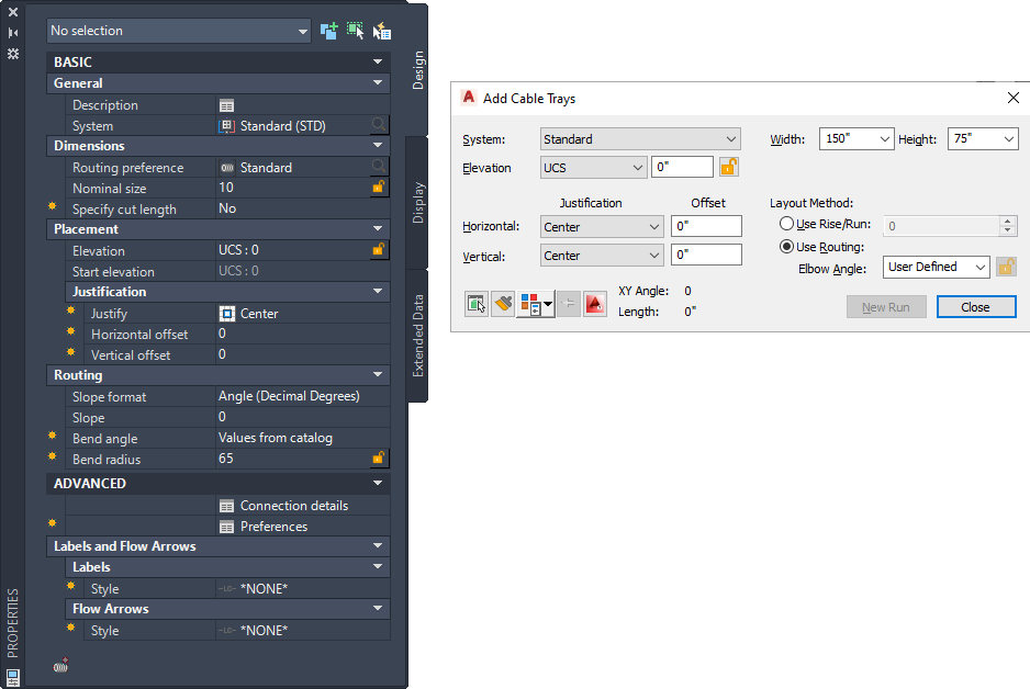
Conduit* (left), cable tray (right)
*Shows expanded properties including parallel routing mode
- Select a system from the following locations:
- For cable tray: In the Add Cable Trays dialog box
System
- For conduit: On the
Properties palette > General
> System >
 > Styles Browser palette
The cable tray and conduit tools have specific, predefined systems, such as Power - 120V or Data. The cable tray or conduit that you draw inherits the system’s properties, such as its design parameters, display properties, and rise and drop style.
- For cable tray: In the Add Cable Trays dialog box
- Specify Routing Preference for Conduits from
Properties palette > General > Dimensions > Routing Preference
>
- Specify dimensions from the following locations:
- For cable tray: In the Add Cable Trays dialog box, at Width and Height
- For conduit: On the Properties palette, under Dimensions, at Nominal size
- Specify how to draw the run:
If you want to… then… draw a run at a specified elevation and offset relative to another object 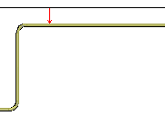
Specifying offset from vertical or horizontal object
enter the desired elevation, and specify justification and offset:
- For cable tray: In the Add Cable Trays dialog box
- For conduit:
Tip: For horizontal offset, select Left, Right, or Center, and then enter the distance between the run and the horizontal object. For vertical offset, select Top, Center, or Bottom, and then enter the distance between the run and the vertical object.draw a run at a specified elevation enter the desired elevation, as described above. Click  (next to Elevation) to prevent the elevation from being changed.
extend a cable tray or conduit run at a specified elevation use Add grips (  ) as described in Adding Conduit or Cable Tray Using Grips. The new segment inherits the elevation and other properties of the original segment.
Tip: Use AutoCAD MEP 2022 toolset snaps to locate valid connection points on objects in the drawing.
) as described in Adding Conduit or Cable Tray Using Grips. The new segment inherits the elevation and other properties of the original segment.
Tip: Use AutoCAD MEP 2022 toolset snaps to locate valid connection points on objects in the drawing. - Specify an angle:
If you want to… then… specify an angle select an angle from the list or enter a different value, as follows: - For cable tray: In the Add Cable Trays dialog box under Use Routing, at Elbow Angle
- For conduit: On the Properties palette, under Routing, at Bend angle
define an angle in the drawing area specify a point in the drawing area using the compass. 
draw with only the specified angle click  next to Elbow Angle (cable tray) or Bend angle (conduit). All segments you draw next will use the same angle.
- To show a vertical rise in the drawing area at a specific elevation, do the following:
- For cable tray: Click
 in the Add Cable Trays dialog box. In the Cable Tray Layout Preferences dialog box on the Routing tab, select Automatically create riser at new Elevation. Click OK, and then enter an elevation in the Add Cable Trays dialog box.
- For conduit: Click
 (Preferences) on the Properties palette. In the Conduit Layout Preferences worksheet, select Automatically create riser at new Elevation. Click OK, and then enter an elevation on the Properties palette.

Automatically create riser at new Elevation selected (default)

Automatically create riser at new Elevation not selected
- For cable tray: Click
- Specify the rise/run angle (cable tray) or slope (conduit) as follows:
- For cable tray: In the Add Cable Trays dialog box, under Layout Method, click Use Rise/Run, and specify a value in degrees.
- For conduit: On the Properties palette, under Routing, specify a value for Slope and Slope format.
- For conduit, you can click
(Connection details) to view the flow direction and connection type for connector #1.
- Continue specifying points to add more segments to your run.
The software inserts the appropriate fittings to connect the segments that you draw. For information about temporarily overriding the default fittings, see Adding Cable Tray or Conduit Fittings Manually.